
Table of contents: Throttle body ↓ Fuel injector ↓ Incoming air temperature sensor ↓ Fuel pressure regulator ↓ Throttle Positioning Module ↓ Throttle potentiometer ↓ Idle speed control switch ↓ Throttle Damper ↓ Oxygen sensor ↓ Coolant temperature sensors ↓ Electronic control unit ↓
Injector Elements
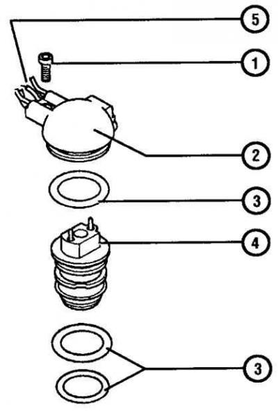
- 1. Mounting screw
- 2. Injector cap
- 3. Sealing ring
- 4. Injector
- 5. Wires
Fuel pressure regulator components
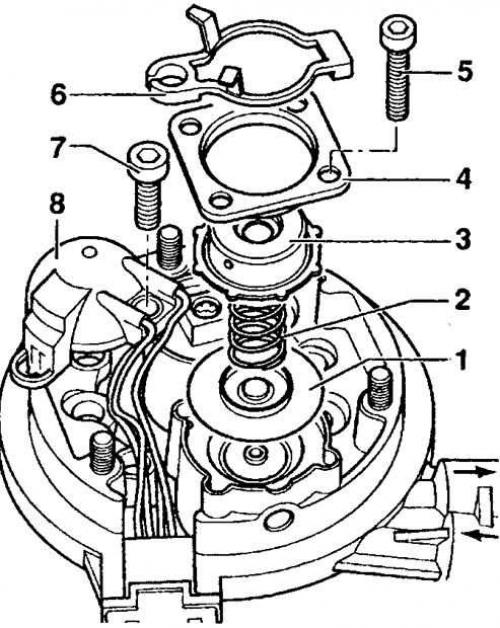
- 1. Membrane
- 2. Spring
- 3. Lid
- 4. Mounting bracket
- 5. Screws
- 6. Guide eye
- 7. Mounting screw
- 8. Cap
Throttle body
Removal
1. Remove the throttle body air duct.
2. Disconnect the fuel hoses and wires from the throttle body.
3. Disconnect the accelerator cable.
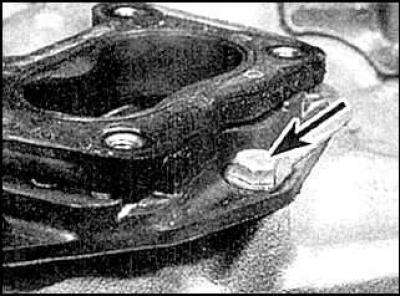
4. Loosen the intermediate flange mounting bolts (arrows) and remove the housing. Remove the intermediate flange if necessary.
Installation
Installation is carried out in the reverse order of removal.
Fuel injector
Removal
1. Remove the throttle body air duct.
2. Disconnect the connection connector.
3. Loosen the mounting screw and remove the cover.
4. Remove the injector and seals.
Installation
Installation is carried out in the reverse order of removal.
Incoming air temperature sensor
The temperature sensor is installed in the injector cover.
Fuel pressure regulator
Installation is carried out in the reverse order of removal.
Throttle Positioning Module
Removal
1. Remove the throttle body air duct.
2. Disconnect the accelerator cable.
3. Disconnect the module connection connector.
4. Loosen the mounting screws and remove the module.
Installation
Installation is carried out in the reverse order of removal.
Throttle potentiometer
The potentiometer is located in the lower section of the throttle valve and is not replaceable.
Examination
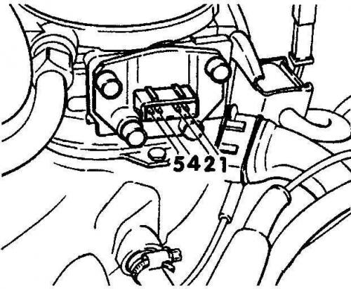
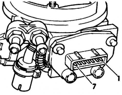
Check that the resistance between terminals 1 and 5 (models with manual transmission, fig. left) or 1 and 7 (models with automatic transmission, fig. on the right) was between 520 and 1300 ohms. When the throttle valve is opened one quarter, the resistance between terminals 1 and 2 should increase from 600 to 3500 ohms, between terminals 1 and 4 (models with manual transmission) or 1 and 6 (models with automatic transmission) from 600 to 6600 Ohm.
Idle speed control switch
The switch is part of the module and is not replaceable. Remove the throttle positioning module.
Throttle Damper
Removal
1. Press the accelerator pedal.
2. Mark the installation position of the damper, unscrew the lock nut and unscrew the damper.
Installation and adjustment
Installation is carried out in the reverse order of removal.
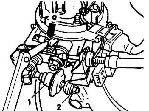
Check that the throttle lever lowers the damper plunger (1) by 4–8 mm when the throttle valve is closed. If necessary, adjust the damper position so that when the throttle valve is fully closed, there is a gap A of 0.05 mm between the throttle valve lock screw and the stop. 2 – lock nut.
Oxygen sensor
Removal
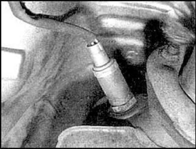
The sensor is installed on the exhaust manifold. Disconnect the sensor connection connector and unscrew the sensor.
Installation
Tighten the sensor to the required tightening torque. Connect the connection connector.
Coolant temperature sensors
Removal
1. Drain about a quarter of the coolant from the engine.
2. Unscrew the corresponding sensor and disconnect the connection connector.
Installation and adjustment
Installation is carried out in the reverse order of removal.
Electronic control unit
Removal
1. Remove the trim panels. Unscrew the mounting screws and remove the ECU housing.
2. Loosen the mounting screws and remove the electronic control unit, disconnecting the connection connector.
Installation and adjustment
Installation is carried out in the reverse order of removal.
This article was previously published on the resource: Audimanual.ru