Table of contents: Engine speed sensor "G28" "arrow" ↓ Boost pressure sensor "G31" with… ↓ Turbocharger Guide Vane Position… ↓ Boost pressure limiting solenoid… ↓ Exhaust gas temperature sensor 1… ↓ System diagram ↓ Mounting position of the pressure… ↓
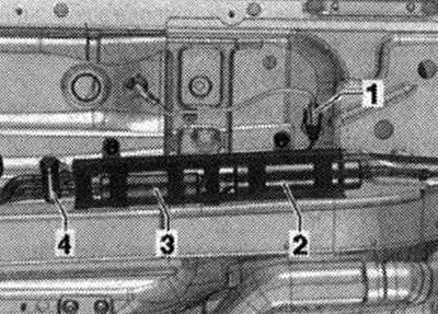
Parts and components on the rear of the engine 1. Sensor 1 exhaust pressure "G450"; 2. Coolant temperature sensor at the radiator outlet "G83"
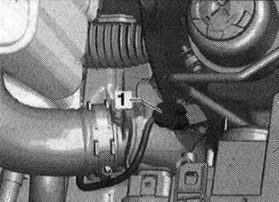
Engine speed sensor "G28" "arrow"
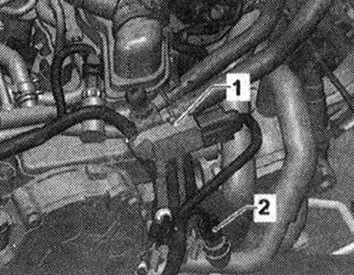
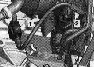
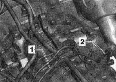
Details 1. Fuel pressure regulator "N₂76"; 2. Electric motor for changing the geometry of the intake manifold "V183"
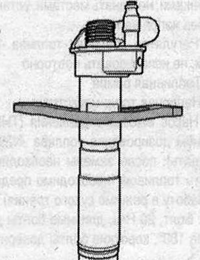
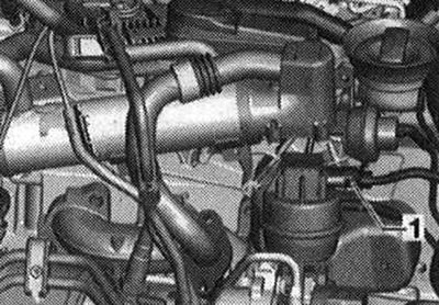
Boost pressure sensor "G31" with intake air temperature sensor "G42" "1"
Single node
Turbocharger Guide Vane Position Sensor "G581" "1"
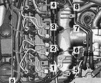
Injectors and glow plugs 1. Injector cylinder 1 "N30"; 2. Injector cylinder 2 "N31"; 3. Injector cylinder 3 "N32"; 4. Injector cylinder 4 "N33"; 5. Glow plug 1 "Q10"; 6. Glow plug 2 "Q11"; 7. Glow plug 3 "Q12"; 8. Glow plug 4 "Q13"; 9. Return fuel line pipes
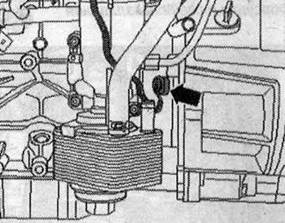
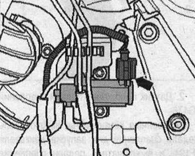
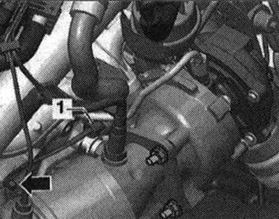
Boost pressure limiting solenoid valve "N75" "arrow".
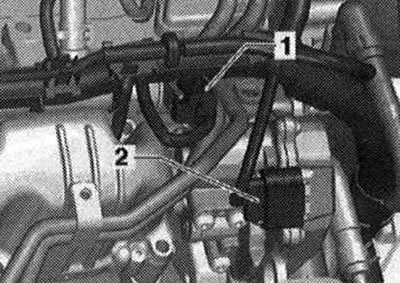
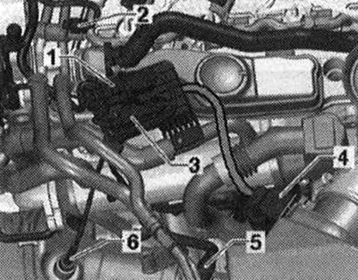
Details 1. Connector for exhaust temperature sensor 1 "G235"; 2. EGR radiator changeover valve "N345"
Additional fuel pump "V393" 1. Additional connector fuel pump "V393" (Can be installed in different places); 2. Fuel filter; 3. Additional fuel pump "V393"; 4. Fuel heating valve
Exhaust gas temperature sensor 1 "G235" "1"
Details 1. Lambda probe connector "G39" with lambda probe heating element "Z19"; 2. Fuel temperature sensor "G81"; 3. Connector of the exhaust gas temperature sensor 3 "G495"; 4. Air flow meter "G70"; 5. Lambda probe "G39" with heating element of lambda probe "Z19"; 6. Exhaust gas temperature sensor 3 "G495"
Exhaust gas temperature sensor 4 "G648" "2" 1. connector for exhaust temperature sensor 4 "G648"
System diagram
Caution: To prevent the injection pump from running in dry friction mode and to quickly start the engine after replacing parts, it is essential to perform the following work: If some parts have been removed or replaced between the fuel tank and the injection pump, it is necessary to first fill the fuel system with fuel. If the fuel pump has been removed or replaced, the fuel line (between the tank and the fuel injection pump) or fuel filter, the fuel system must be bled before the first engine start. If the high-pressure fuel pump has been removed or replaced, the fuel system must be bled before the first engine start. Starting the engine without first filling the fuel system will damage the high-pressure fuel pump.
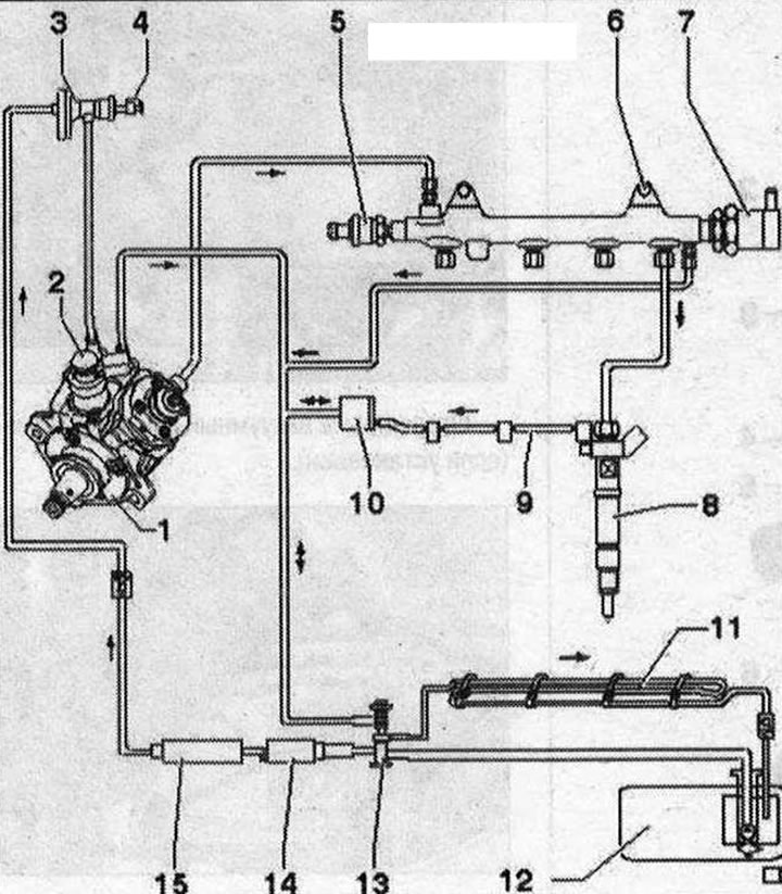
System diagram 1. High pressure pump (HPFP), after replacement it is "necessary" to fill with fuel (it is necessary to prevent operation in dry friction mode); 2. Fuel metering valve "N₂90", do not open; 3. Mesh filter; 4. Fuel temperature sensor "G81"; 5. Fuel pressure sensor "G247", 100 Nm; 6. Fuel rail; 7. Fuel pressure regulator "N₂75", 80 Nm, do not reuse; 8. Nozzles; 9. Return fuel lines, return fuel lines cannot be disassembled, replacement is possible only in assembly with a pressure reducing valve, after replacement it is necessary to let the engine idle for about 2 minutes to remove air from the fuel system, then check the return fuel lines for leaks 10. Pressure reducing valve, the task of the pressure reducing valve is to maintain the residual pressure in the return fuel lines at a level of 10 bar. This is necessary for the normal operation of the injectors, the pressure reducing valve is allowed to be replaced only in assembly with return fuel lines, after replacement it is necessary to let the engine idle for about 2 minutes to remove air from the fuel system; 11. Fuel radiator, mounted on the bottom; 12. Fuel tank, with fuel booster pump "G6"; 13. Fuel heating valve; 14. Additional fuel pump "V393"; 15. Fuel filter
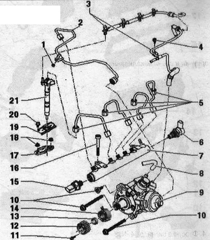
Parts and components of the power supply system 1. Bolt, 10 Nm; 2. High pressure line, 25 Nm, between the high pressure pump and the fuel rail; 3. Return fuel lines to the fuel tank, the return fuel line must not be bent, must not be damaged or clogged, return fuel lines must not be disassembled, replacement is only possible in assembly with the pressure reducing valve, the task of the pressure reducing valve is to maintain residual pressure in the return lines (adjustable quantity) at 10 bar. This is necessary for normal operation of the injectors, after replacement it is necessary to let the engine idle for about 2 minutes to remove air from the fuel system, then check the return fuel lines for leaks; 4. Bolt, 10 Nm; 5. High pressure pipes, 25 Nm, between the fuel rail (Battery pressure) and nozzles, do not swap, install without stress; 6. Fuel pressure regulator "N₂76", 80 Nm, do not reuse; 7. Fuel rail; 8. Pressure fuel main; 9. High pressure pump (HPFP), with fuel metering valve "N₂90" (do not open), after replacement it is necessary to fill with fuel (it is necessary to prevent operation in dry friction mode); 10. Bolt, 20 Nm, long bolts turn 180°, short bolts turn 90°; 11. Bolt, 20 Nm; 12. Toothed pulley of the fuel injection pump; 13. Nut, 95 Nm; 14. Hub, with a timing rotor, when loosening and tightening use the stop "T10051", for removal use the puller "T40064"; 15. Fuel pressure sensor "G247", 100 Nm; 16. Bolt, 22 Nm; 17. Pressure plate. Re-installed injectors and pressure plates must be installed in the same cylinder. If the injector is replaced with a new one, the pressure plate must also be replaced; 18. Hexagon nut with flange, for pressure plate, 10 Nm; 19. Nozzle cover; 20. Bolt, 5 Nm; 21. Nozzle
Mounting position of the pressure plate