
Table of contents: Accelerator Pedal Position Sensor… ↓ Brake light switch "F" and brake… ↓ Radiator pump of the recirculation… ↓ Coolant temperature sensor "G62" "2" ↓ Hall sensor "G40" ↓
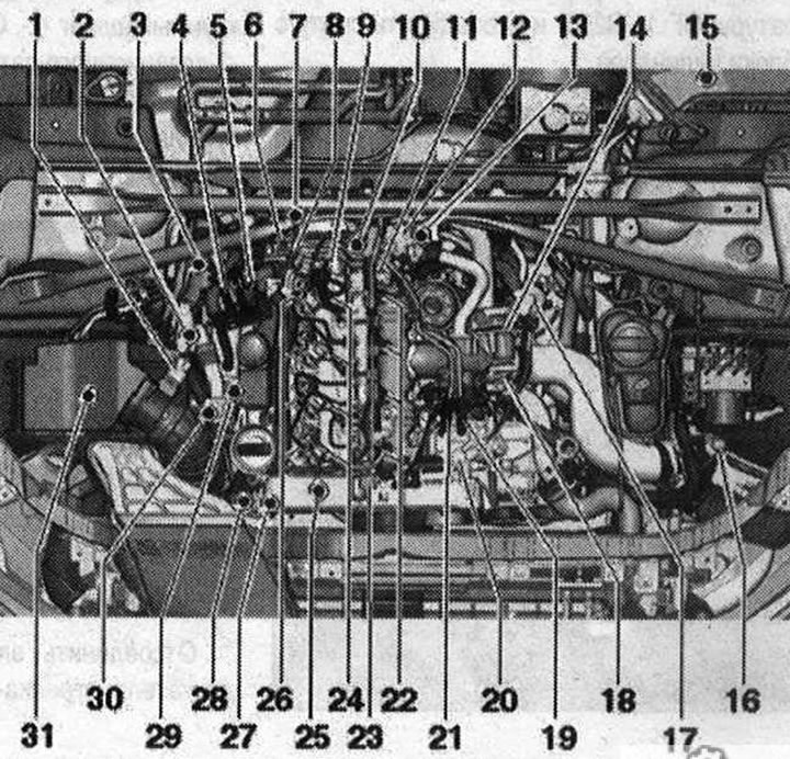
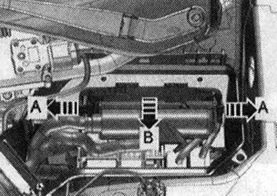
Overview of installation locations Parts A to J are not shown in the diagram. 1. Air flow meter "G70"; 2. Lambda probe "G39" with heating element of lambda probe "Z19"; 3. Exhaust gas temperature sensor 3 "G495"; 4. Connector of the exhaust gas temperature sensor 3 "G495"; 5. Lambda probe connector "G39"; 6. Sensor 1 exhaust pressure "G450", after replacement it is necessary to perform adaptation; 7. Coolant temperature sensor at the radiator outlet "G83"; 8. Fuel temperature sensor "G81", installation location: in the pressure fuel line; 9. Pressure reducing valve, the task of the pressure reducing valve is to maintain the residual pressure in the return fuel line at a level of 10 bar. This is necessary for the normal operation of the injectors, the pressure reducing valve may only be replaced as a set with the return fuel lines, after replacement it is necessary to let the engine idle for about 2 minutes to remove air from the fuel system; 10. Coolant temperature sensor "G62"; 11. Fuel pressure regulator "N₂76", 80 Nm; 12. Electric motor for changing the geometry of the intake manifold "V183", with the sensor for changing the geometry of the intake manifold flaps "G513"; 13. Engine speed sensor "G28", 4.5 Nm; 14. Electric motor for driving the air flap/intake flaps "V157", with air flap potentiometer "G69"; 15. Used engine "J623"; 16. Boost pressure sensor "G31", single unit with intake air temperature sensor "G42"; 17. EGR radiator pump "V400"; 18. EGR valve "N18" with EGR potentiometer "G212"; 19. Fuel return line connector; 20. Fuel injection pump with fuel metering valve "N₂90", do not open fuel metering valve "N₂90"; 21. Fuel pressure line connector; 22. Glow plugs; 23. Fuel pressure sensor "G247", 100 Nm; 24. Nozzles; 25. Hall sensor "G40"; 26. Return fuel lines, return fuel lines cannot be disassembled, replacement is possible only in assembly with a pressure reducing valve, after replacement it is necessary to let the engine idle for about 2 minutes to remove air from the fuel system, then check the tightness of the return fuel lines; 27. Electromagnetic boost pressure limiting valve "N75"; 28. EGR radiator changeover valve "N345"; 29. connector for exhaust temperature sensor 1 "G235"; 30. Turbocharger guide vane position sensor "G581"; 31. Air filter bypass flap valve "N₂75", parts (bypass flap with air filter bypass flap valve "N₂75") are not installed in all equipment variants; A. Relay and fuse block in the switch block in the left water drain box; B. Low power heating relay "J359" and High power heating relay "J360"; C. Brake light switch "F" and brake pedal switch "F47", in the footwell on the brake pedal; D. Clutch pedal position sensor "G476", only for vehicles with manual transmission; E. Accelerator pedal position sensor "G79" and accelerator pedal position sensor 2 "G185"; F. Additional fuel pump "V393"; G. Exhaust gas temperature sensor 1 "G235". Installation location: on turbocharger, 45 Nm; N. Exhaust temperature sensor 4 "G648", 45 Nm; I. Connector of the exhaust gas temperature sensor 4 "G648"; J. Diesel particulate filter, installed on the bottom, after replacement it is necessary to perform adaptation
After replacing the exhaust gas pressure sensor 1 "G450" and / or the particulate filter, it is necessary to perform an adaptation. The adaptation is described in the guided fault finding or guided functions, using a tester. Installation location: engine control unit "J623". In the engine compartment in the left switching unit.
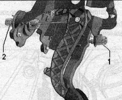
Accelerator Pedal Position Sensor "G79" and Accelerator Pedal Position Sensor 2 "G185"
The accelerator pedal position sensor "G79" and the accelerator position sensor 2 "G185" are integrated into the accelerator pedal module and cannot be replaced separately.
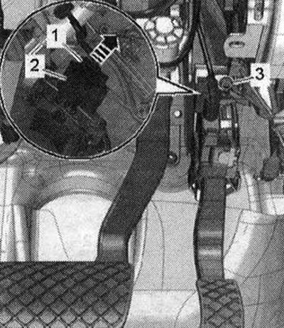
Brake light switch "F" and brake pedal switch "F47" "1"
2. Clutch pedal position sensor "G476"
Built-in components: Clutch pedal switch for engine start "F194" and clutch pedal switch "F36" (only for manual transmission)
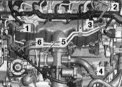
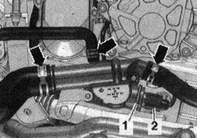
Installation locations 1. Fuel pressure sensor "G247"; 2. Fuel pressure regulator "N₂76"; 3. Electric motor for changing the geometry of the intake manifold "V183" with the sensor of the position of the flaps of changing the geometry of the intake manifold "G513"; 4. Air damper drive motor "V157" with air damper potentiometer "G69"; 5. EGR valve "N18" with EGR potentiometer "G212"; 6. Fuel metering valve "M290"
Radiator pump of the recirculation system OF "V400--1"
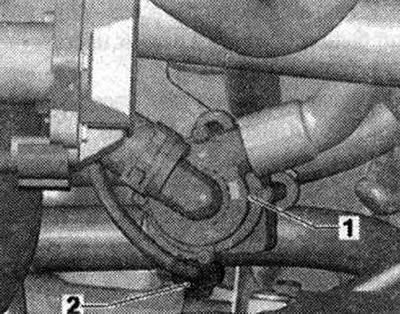
Coolant temperature sensor "G62" "2"
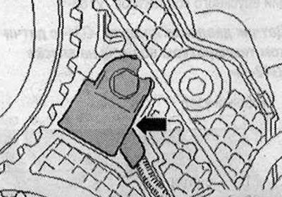
Hall sensor "G40"
The original text is available on the website: AudiManual