
Table of contents: Left cylinder head cover. Sequence… ↓ Oil dipstick guide tube ↓ Removal the left cylinder head cover ↓ Installation ↓ Removal the right cylinder head cover ↓ Installation ↓
The figure shows the cylinder head of the 2nd row of cylinders (left).
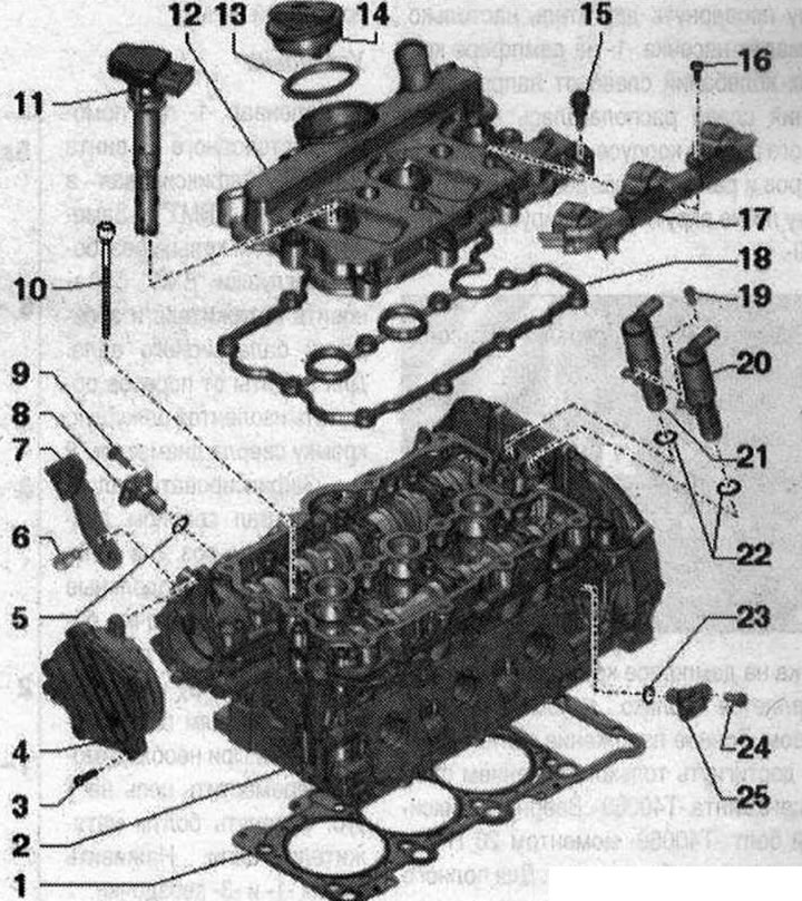
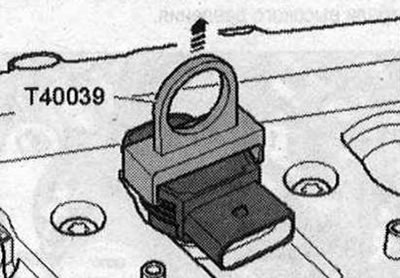
Cylinder head 1. Cylinder head seal. Installation position: the part number faces the cylinder head. After replacement, replace the coolant and oil; 2. Cylinder head. Check for distortion. After replacement, replace coolant and oil; 3. Bolt; 4. Vacuum pump; 5. Sealing ring. Replace; 6. Bolt. 20 Nm; 7. Engine suspension eye; 8. Intake camshaft Hall sensor. Cylinder bank 1 (right) Hall sensor "G40"; Cylinder bank 2 (left) Hall sensor 2 "G163"; 9/24. Bolt. 9 Nm; 10. Bolt. Replace. Tighten in 3 stages: 1) Tighten to 40 N·m; 2) turn 90°; 3) turn 90°; 11. Ignition coil. Remove using the puller "T40039"; 12. Cylinder head cover; 13. Gasket; 14. Lid; 15. Bolt. Replace if seal is damaged; 16. Bolt; 17. Ignition coil plug bar; 18. Cylinder head cover gasket. Replacement if damaged or leaking; 19. Bolt. 2.5 Nm; 20. Electromagnetic valve of the variable valve timing system, exhaust side. Cylinder bank 1 (right) Valve 1 of the variable valve timing system, exhaust "N318". Cylinder bank 2 (left) Valve 2 of the variable valve timing system, exhaust "N319"; 21. Solenoid valve of the variable valve timing system on the intake side. Cylinder bank 1 (right) Valve 1 of the variable valve timing system "N₂05". Cylinder bank 2 (left) Valve 2 of the variable valve timing system "N₂08"; 22. O-ring seal. Replace; 23. Sealing ring. Replace; 25. Exhaust camshaft Hall sensor.
Cylinder bank 1 (right) Hall sensor 3 "G300". Cylinder bank 2 (left) Hall sensor 4 "G301"
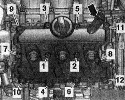
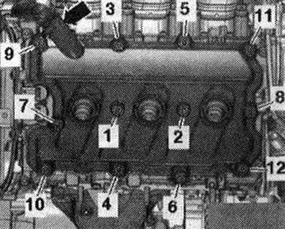
Left cylinder head cover. Sequence and tightening torque
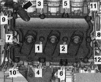
Tighten the bolts in sequence "1...12" to a torque of 9 Nm.
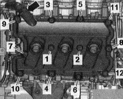
Tighten the bolts in sequence "1...12" to a torque of 9 Nm.
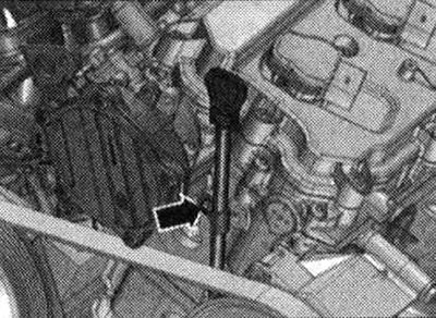
Oil dipstick guide tube
Tighten the arrow bolt to 9 Nm.
Removal the left cylinder head cover
Remove the engine compartment covers.
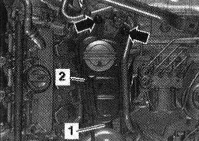
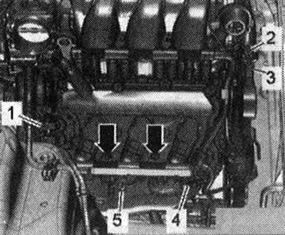
Unscrew the bolts "arrows". Disconnect the electrical connector of the low coolant level indicator sensor "F66" and put aside the coolant expansion tank with the connected hoses "1, 2". Make sure that the cooling system hose "2" is not bent. Unscrew the bolts "arrows" and disconnect the electrical connectors from the ignition coils on the left cylinder head. Disconnect the electrical connector "1" of the Hall sensor 2 "G163" and "4" of the Hall sensor 4 "G301". Disconnect the electrical connectors "3" of the valve 2 of the timing phase adjustment system "N₂08" and the valve 2 of the exhaust valve timing system "N319", to do this, squeeze the connector latches and remove both connectors together. Unscrew the bolt "5" of the ground cable.
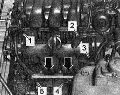
Put aside the electrical wiring harness. Ignore "Pos. 2". Remove the ignition coils using the "T40039" puller.
Remove the crankcase ventilation hose "arrow" by pressing the release buttons. Unscrew the bolts in the sequence "12...1" and remove the left cylinder head cover.
Cars in set for USA: Do not open the hose connection "arrow".
Unscrew the bolts in the sequence "12...1" and put aside the left cylinder head cover with the connected hose "arrow" of the crankshaft ventilation.
Installation
Install in reverse order, replacing the O-ring. Replace the damaged cylinder head cover gasket. If the gasket is damaged, replace the cylinder head cover bolts. Clean the mounting surfaces; there should be no oil or grease on them. Tighten the bolts of the left cylinder head cover.
Removal the right cylinder head cover
Remove engine compartment covers. Remove air filter housing. Unscrew "arrow" bolts and disconnect electrical connectors from ignition coils on right cylinder head.
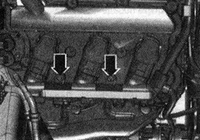
Disconnect electrical connector "5" of Hall sensor 3 "G300". Disconnect electrical connectors "1" of valve 1 of the camshaft phase adjustment system "N₂05" and valve 1 of the exhaust camshaft phase adjustment system "N318". To do this, squeeze the connector latches and remove both connectors together. Press aside the bundle of electrical wires. Ignore "Pos. 2, 3, 4".
Remove the ignition coils with the puller "T40039". Remove the crankcase ventilation hose "arrow" by pressing the release buttons. Unscrew the bolts in the sequence "12...1" and remove the right cylinder head cover.
Cars in set for USA: Do not open the hose connection "arrow"!
Unscrew the bolts in the sequence "12...1" and put aside the right cylinder head cover with the connected hose "arrow" of the crankcase ventilation system.
Installation
Installation in reverse order, taking into account the following: Replace the O-ring. Replace the damaged cylinder head cover gasket. If the gasket is damaged, replace the cylinder head cover bolts. Clean the mounting surfaces; there should be no oil or grease on them. Tighten the bolts of the right cylinder head cover. Install the air filter housing.