
Table of contents: Emptying the oil filter housing ↓ Removal and installation the oil… ↓ Removal and installation the oil… ↓ Removal and installation the oil pan ↓ Removal and installation the balance… ↓
Note: If, during repairs, an increased amount of metal shavings or wear products in the engine oil are found in the engine, then to avoid subsequent damage, the lubrication channels should be thoroughly cleaned and the oil cooler should be replaced.
1. The installation details of the lubrication system components are shown in the illustrations.
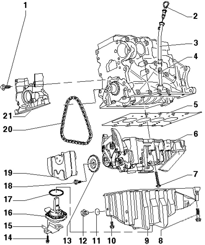
27.1a. Oil pan and balance shaft module installation details 1. Holder mounting bolts 21, 15 Nm; 2. Engine oil level dipstick; 3. Intermediate tube of the probe 2; 4. Guide tube of the feeler gauge 2; 5. Spacer; 6. Balance shaft module with oil pump with 12 bar pressure reducing valve; 7. Module 6 mounting bolts (different lengths), 15 Nm, then tighten to 90° angle, use new bolts; 8, 10. Pan mounting bolts 9, 15 Nm; 9. Engine oil pan; 11. Plug sealing ring 12; 12. Threaded drain plug, 30 Nm, must be replaced; 13. Oil pump sprocket; 14. Sensor mounting bolt 16, 10 Nm; 15. Protective cap of sensor 16; 16. Engine oil level and temperature sensor; 17. Sensor sealing ring 16, subject to replacement; 18. Sprocket mounting bolt 13, 20 Nm, then tighten to an angle of 90°, use a new bolt; 19. Chain cover 20; 20. Oil pump drive chain; 21. Front crankshaft oil seal holder
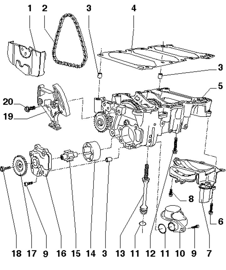
27.1b. Balance shaft module and oil pump installation details 1. Chain cover 2; 2. Oil pump drive chain; 3. Mounting sleeve; 4. Spacer; 5. Balance shaft module with oil pump; 6. Cover fastening bolt 7.9 Nm; 7. Oil soother; 8. Cover mounting bolts 7, 40 Nm; 9. Cover fastening bolt 16.8 Nm; 10. Oil intake with mesh filter; 11. Sealing ring, subject to replacement; 12. Module 5 mounting bolts (different lengths), 15 Nm, then tighten to 90° angle, use new bolts; 13. Bolt with seal for fastening module 5, 15 Nm, then tighten to an angle of 90°, use a new bolt; 14/15. Outer/inner rotor of oil pump; 16. Oil pump cover; 17. Oil pump sprocket; 18. Sprocket mounting bolt 17, 20 Nm, then tighten to an angle of 90°, use a new bolt; 19. Chain tensioner 2 with bar; 20. Tensioner mounting bolts 19, 15 Nm
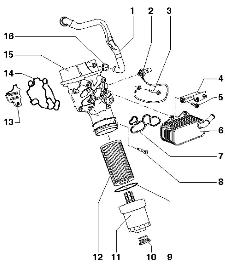
27.1c. Oil filter and oil cooler installation details 1. PCV tube; 2. Oil pressure sensor 1.4 bar, black, 21 Nm; 3. Sensor ground wire mounting bolt 2, 15 Nm; 4. Bracket; 5. Bracket mounting bolt 4, 15 Nm; 6. Oil cooler; 7. Oil cooler gasket, subject to replacement; 8. Holder mounting bolts 15, 15 Nm; 9. Sealing ring, subject to replacement, installed with the convex side facing the engine; 10. Body plug 11; 11. Oil filter housing; 12. Oil filter element; 13. Oil separator; 14. Holder gasket 15, subject to replacement; 15. Oil filter holder (with pressure reducing valve, 4 bar); 16. Spring clamp
Emptying the oil filter housing
2. Unscrew the dust cap (arrow on the illustration) from the oil filter housing.
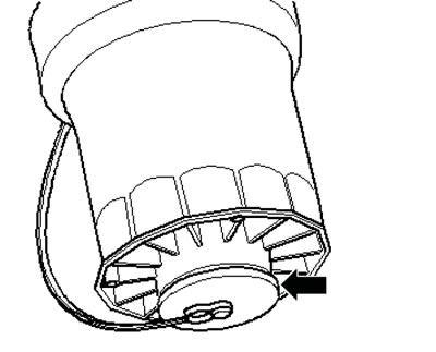
27.2. Oil filter housing dust cap
3. Direct the hose of the oil drain adapter #T40057 into the oil collection pan and screw the adapter into the oil filter housing (see illustration).
Note: When screwing in the oil drain adapter No. T40057, a valve opens in the oil filter housing, and when unscrewing the adapter, the valve automatically closes again.
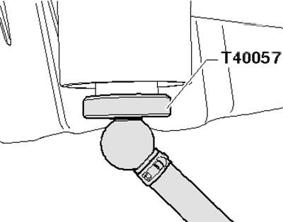
27.3. Adapter for draining the oil filter housing
4. Allow the oil to drain, unscrew the adapter and install the dust cap.
Removal and installation the oil cooler
5. Remove the top engine cover as shown in the illustration 17.10. Remove the cap from the engine cooling system expansion tank.
6. On models with independent/additional heating, remove the screw (1 in illustration 5.4) its exhaust pipe on a sound-insulating casing.
7. Unscrew the fasteners (1 and 2 in Illustration 5.5) and remove the front soundproofing screen. If present, unscrew the fasteners (3) and remove the rear soundproofing screen.
8. Drain the coolant (see Chapter 3), the exhaust pipe and the fuel distribution line (see Chapter 4).
9. Remove the connector holder fastener (arrows in the illustration) on the water pipe.
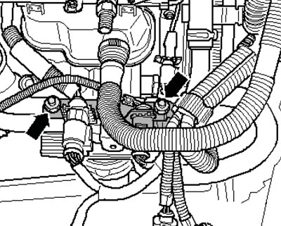
27.9. Fastening the connector holder
10. Disconnect the coolant supply hose (1 in the illustration) and unscrew the screw (2).
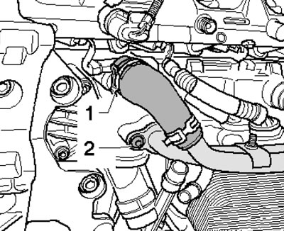
27.10. Coolant hose
11. Disconnect the water hoses (arrows in the illustration) from the water pipe, unscrew the bolt (1) and remove the water pipe.
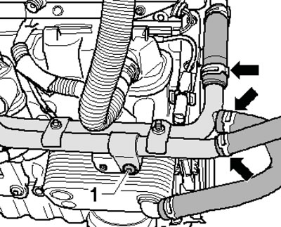
27.11. Removing the water pipe
12. Remove the bolts (see illustration) and remove the oil cooler.
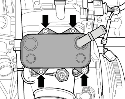
27.12. Oil cooler mounting
13. Installation is carried out in the reverse order of dismantling the components. Use new gaskets and sealing rings. Finally, fill the cooling systems (see Chapter 3).
Removal and installation the oil filter holder
14. Follow the steps described in paragraphs 5-7.
15. Drain the coolant (see Chapter 3).
16. Mark the alternator belt with chalk or a felt-tip pen to indicate the direction of rotation so that you can install the belt in the same way. Loosen the belt tension by turning the tensioner in the direction of the arrow (see illustration 17.18). Secure the tensioner clamps No. T40098 and remove the alternator belt.
17. Remove the bolts (see illustration 21.4) and remove the alternator belt tensioner with the engine lifting eye. Remove the alternator (see Chapter 5).
18. Remove the exhaust pipe and fuel rail (see Chapter 4).
19. Remove the holder fastener.
20. Remove the oil cooler as described in paragraphs 9-12.
21. Disconnect the tube (1 in the illustration) PCV and ground wire (2) D/V oil pressure. Loosen bolts (arrows) and remove oil filter holder.
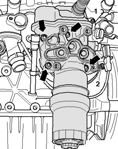
27.21. Fastening the oil filter holder
22. Installation is carried out in the reverse order of dismantling the components. Use new gaskets and sealing rings. Finally, fill the cooling systems (see Chapter 3).
Removal and installation the oil pan
23. Remove the top engine cover as shown in the illustration 17.10.
24. Remove the engine compartment seal on the connecting edges of the wings. To avoid damaging the connecting edges of the wings, use the No.10-222-A hanging device to place the No. T40045 wing gaskets on both sides between the connecting edges of the wings and the vertical sheet below (see illustration 16.6).
25. Install crossmember No.10-222-A with adapters No.10-222/3 on the edge of the wing, hook the running bolts to the lifting eyes (see illustration) and slightly tighten the engine using the running bolts.
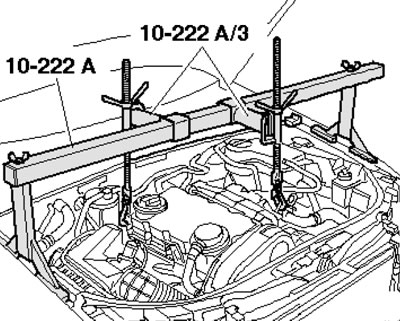
27.25. Hanging the engine
26. Remove the alternator drive belt (see Section 19).
27. On models with independent/additional heating, remove the screw (1 in illustration 5.4) its exhaust pipe on a sound-insulating casing.
28. Unscrew the fasteners (1 and 2 in Illustration 5.5) and remove the front soundproofing screen. If present, unscrew the fasteners (3) and remove the rear soundproofing screen.
29. Pump out the oil from the engine.
30. Remove the bolts (see illustration) and remove the torque support from the oil pan. Loosen the nuts (1) securing the turbocharger return oil line to the oil pan.
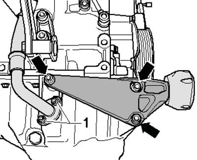
27.30. Fastening the torque stop and return oil line (1)
31. Perform the actions described in paragraphs 47-49 Section 5.
32. Disconnect the connector (1 in the illustration) front left ride height sensor.
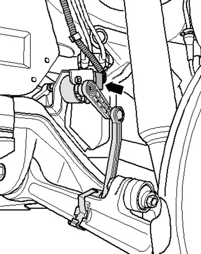
27.32. Front left ride height sensor connector
33. Perform the actions described in the paragraphs 15-17 Section 16.
34. Slowly lower the subframe on the transmission jack. Pull the engine up slightly using the lead screws of the #10-222A engine jack, making sure there is free play in the shift linkage/lever system and the exhaust system (see illustration 27.25).
35. Remove the bolts (see illustration 5.52) fastening the transmission to the oil pan.
36. Unscrew the M10 bolts (arrows in illustration 16.21), loosen the bolts (1-18) crosswise, unscrew all the bolts and remove the oil pan, lightly tapping it with a rubber-faced hammer if necessary.
37. Installation is performed in the reverse order of component dismantling. Please note the following features.
38. Prepare the following new parts: oil pan gasket, lip seals, sealing rings and bolts/screws tightened to a certain angle. Remove any remaining sealant from the mating surfaces of the oil pan and cylinder block, clean all seating surfaces from oil and grease.
39. Apply a 2-3 mm diameter bead of sealant to the clean surface of the oil pan as shown in the illustration.
Note: In the area of the threaded holes, the bead of sealant should run along the inside; in the area of the rear sealing flange (arrows), apply the sealant with particular care. The balance shaft module and oil pan must be installed within 5 minutes after applying the sealant.
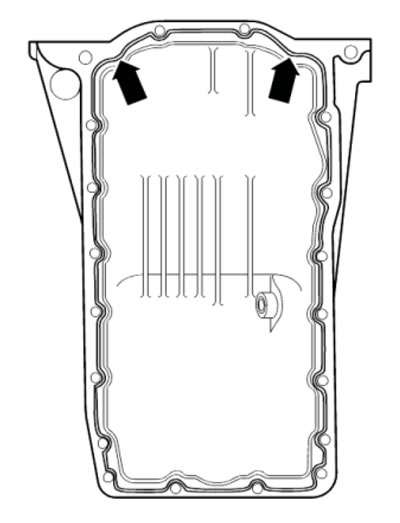
27.39. Sealant application diagram
40. Immediately after applying the sealant, install the oil pan and tighten its mounting bolts as shown in the illustration 16.21 sequence in several stages: first bolts 1-18 - crosswise with a force of 5 Nm, then - bolts fastening the pan to the transmission with a force of 45 Nm, then - bolts M10 (arrows) with a force of 40 Nm, and finally - bolts 1-18 crosswise with a force of 15 Nm.
41. When installing the oil pan (3 in the illustration 16.36) on the removed engine, pay attention to the fact that the pallet should be flush with the intermediate shield (1), i.e. the pallet should protrude beyond the cylinder block (2) by the size (a) - 0.8 mm. After installation, the sealant should dry for about 30 minutes. Only then can you fill in the engine oil.
42. Install the subframe and stabilizer (see Chapter 10).
Removal and installation the balance shaft module with oil pump
43. Remove the engine oil pan (see subsection above).
44. Set the piston of the first cylinder to the TDC position of the end of the compression stroke (see illustration 22.9).
45. Remove the sprocket cover by carefully pressing the clips in the holes with a screwdriver (see illustration 16.23).
46. Loosen the bolt (18 in illustration 27.1a) fastening the oil pump sprocket by one turn. Loosen the tensioner bar with a screwdriver (arrow in illustration 16.24) and secure the damper bar with a 3 mm rod wrench (1).
47. Remove the oil pump sprocket and remove the chain from the balance shaft drive.
48. Remove the bolts (1 and 2 in the illustration) fastenings of the oil separator and remove it.
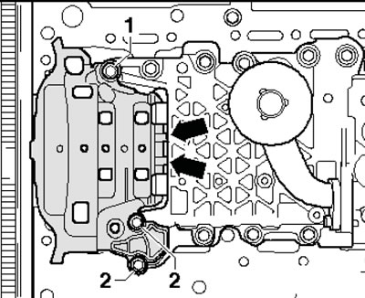
27.48. Oil damper mounting
49. Loosen the balance shaft module mounting bolts and remove it (see illustration). The installation process is described below.
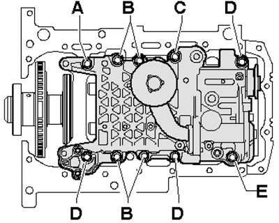
27.49. Balance shaft module mounting bolts A. Bolt M7x40; B. Bolt M7x70; S. Bolt M7x90; D. Bolt M7x55; E. Threaded plug with sealing ring
50. Tighten the tensioner piston by hand (see illustration).
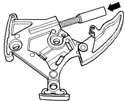
27.50. Tightening the tensioner by hand
51. Press the tensioner bar in the direction of the arrow (see illustration) and secure it with a 3 mm rod wrench (1).
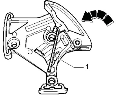
27.51. Fixing the tensioned tensioner
52. Prepare new balance shaft module mounting bolts and a new sealing ring for the module mounting bolt. Place the spacer (4 in illustration 27.1b) on the centering bushings of the balance shaft module and install the module with the oil pump and spacer. Tighten the new bolts (they have different lengths) fastening the module in sequence from the inside out (see illustration 27.49) in several stages: first by hand, then with a force of 15 Nm, and finally, pull them to an angle of 90°.
53. Install the oil separator into the grooves (arrows in illustration 27.48), tighten bolt (1) to 21 Nm and bolts (2) to 9 Nm.
54. Screw the central bolt into the crankshaft and turn the shaft so that the piston of the first cylinder is in the TDC position (see illustration 22.9).
55. Put a mark (arrow on the illustration) on the balance shaft sprocket opposite the locking hole, lock the sprocket in this position using the No. T10027 rod wrench and put the chain on the balance shaft sprocket. Install the oil pump sprocket and tighten its mounting bolt by hand.
Note: The oil pump sprocket can only be installed in one position; during installation, only the oil pump can be turned.
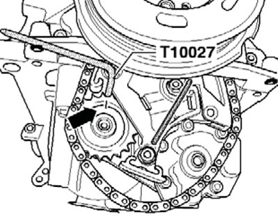
27.55. Fixing the balance shaft sprocket
56. Remove key No. T10027 and rod key (1 in illustration 16.24). Tighten the oil pump sprocket bolt to the required torque and install the engine oil pan.