



Table of contents: Petrol models 1.6, 1.8 and 2.0 l… ↓ Petrol models 2.0 TFSI ↓ Diesel models 1.9 and 2.0 l ↓
Note: Description is given only for the most common engines; on other models, removal and installation of the generator is carried out in a similar manner.
Petrol models 1.6, 1.8 and 2.0 l (MPI and FSI)
1. Disconnect the negative cable from the battery.
2. Open the expansion tank cap and remove the upper decorative engine cover.
3. On models with independent/additional heating, unscrew the bolts (arrows in illustration 5.4 Chapter 2) its exhaust pipe from the soundproofing screen.
4. Release the fasteners (1 and 2 in Illustration 5.5 Chapter 2) and remove the front sound insulation.
5. Remove the retainer (1 in illustration 5.7 Chapter 2) and separate the coolant temperature sensor (2) at the radiator outlet. Drain the coolant from the radiator into a previously prepared container.
6. Disconnect the upper coolant hose from the tube (see illustration).
12.6. Upper coolant hose
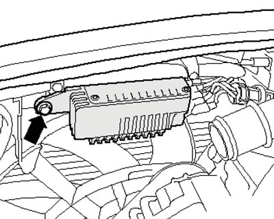
7. Unscrew the bolt (see illustration), remove the fan control unit and set it aside.
12.7. Fan control unit mounting bolt
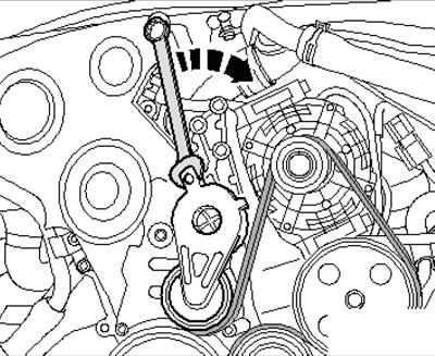
8. Turn the alternator drive belt tensioner in the direction of the arrow (see illustration) and remove the belt from the generator. Release the tensioner.
12.8. Removing the alternator drive belt
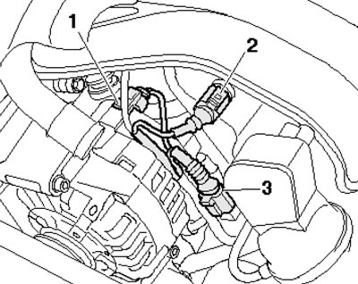
9. Disconnect the connector (1 in the illustration). On 2.0L models, additionally disconnect connectors (2 and 3).
12.9. Electrical wiring connectors
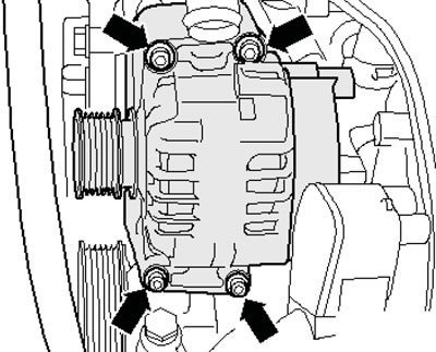
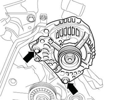
10. Remove the bolts (see illustration) and tilt the generator forward.
12.10. Generator fastening
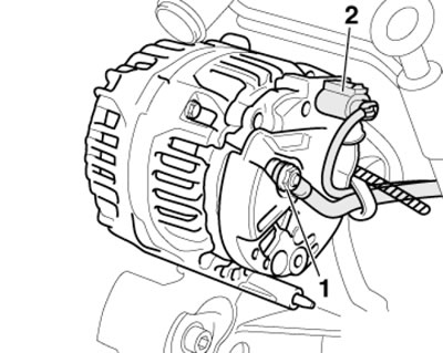
11. Disconnect the connector (2 in the illustration), remove the nut (1) of terminal 30 and remove the generator.
12.11 Generator connections
12. Installation is carried out in the reverse order of dismantling the components.
Petrol models 2.0 TFS
I13. Disconnect the negative cable from the battery.
14. Remove the upper decorative engine cover (see Chapter 2).
15. Turn the alternator drive belt tensioner in the direction of the arrow (see illustration 17.18 Chapter 2) and lock it in this position with pin T40098. Remove the generator drive belt.
16. Disconnect the air hose (2 in illustration 17.22 Chapter 2) from the intake manifold.
17. Remove the bolts (see illustration 12.10) and tilt the generator forward.
18. Disconnect the connector (2 in illustration 12.11), remove the nut (1) of terminal 30 and remove the generator.
19. Installation is carried out in the reverse order of dismantling the components.
Diesel models 1.9 and 2.0 l
20. Remove the upper decorative engine cover (see Chapter 2). On 2.0 DOHC engines, remove the air cleaner intake (see Section 16 Chapter 1) and drive belt cover (see Chapter 2).
21. Pull the tensioner roller in the direction of the arrow (see illustration 40.23 Chapter 2) and remove the generator drive belt.
22. Disconnect the connector (2 in illustration 12.11), remove the nut (1) of terminal 30 and move the wiring to the side.
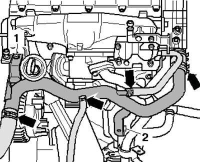
23. On 2.0 DOHC engines, move the electrical wiring to the side on the upper coolant pipe, unscrew the bolt (1 and 2 in the illustration) and move the upper coolant pipe slightly to the left.
12.23. Upper coolant pipe connections (dOHC models only)
24. Remove the bolts (see illustration) and remove the generator.
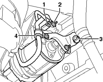
12.24. Generator fastening