
Table of contents: Petrol models 1.6, 1.8 and 2.0 l… ↓ Petrol models 2.0 TFSI ↓ Diesel models 2.0L DOHC ↓
Petrol models 1.6, 1.8 and 2.0 l (MPI and FSI)
1. Disconnect the negative cable from the battery.
2. On models with independent/additional heating, unscrew the bolts (arrows in illustration 5.4 Chapter 2) its exhaust pipe from the soundproofing screen.
3. Release the fasteners (1 and 2 in Illustration 5.5 Chapter 2) and remove the front sound insulation.
4. Give the nut (2 in the illustration) terminals B+, disconnect the connector (1) of terminal 50. If present, separate the insulation of the positive terminal of the starter. Unscrew the bolts of the clamp (4) and bracket (3) of the starter on the cylinder block and on the starter.
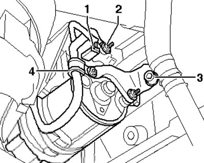
13.4 Starter connections
5. Remove the bolts (1 in the illustration), slide the starter down and remove it.
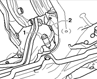
13.5. Starter fastening
6. Installation is carried out in the reverse order of dismantling the components.
Petrol models 2.0 TFSI
7. Disconnect the negative cable from the battery.
8. On models with independent/additional heating, unscrew the bolts (arrows in illustration 5.4 Chapter 2) its exhaust pipe from the soundproofing screen.
9. Remove the right front drive shaft heat shield (see illustration 5.43 Chapter 2).
10. Remove the bolts (1 and 2 in Illustration 13.5), remove the starter and tilt it to the side.
11. Disconnect the connector (3 in illustration 17.40 Chapter 2), loosen the clamp nut (1), nut (2) and remove the electrical wiring. Loosen the bracket fastener on the starter and on the cylinder block (3), remove the starter.
12. Installation is carried out in the reverse order of dismantling the components.
Diesel models 2.0L DOHC
13. Disconnect the negative cable from the battery.
14. On models with independent/additional heating, unscrew the bolts (arrows in illustration 5.4 Chapter 2) its exhaust pipe from the soundproofing screen.
15. Release the fasteners (1 and 2 in Illustration 5.5 Chapter 2) and remove the front sound insulation.
16. Remove the sound insulation in the right front wheel arch (see illustration 40.46 Chapter 2) and the heat shield of the right front drive shaft (see illustration 5.43 Chapter 2).
17. Remove the bolts (1 in the illustration) and remove the turbocharger support.
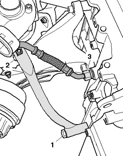
13.17. Fasteners (1 and 2) of the turbocharger support
18. Remove the bolts (1 and 2 in Illustration 13.5) starter mounts.
Note: On CVT models, bolt (1) is installed from the reverse side.
19. Disconnect the connector (3 in illustration 17.40 Chapter 2), loosen the clamp nut (1), nut (2) and remove the electrical wiring. Loosen the bracket fastener on the starter and on the cylinder block (3), remove the starter.
20. Installation is carried out in the reverse order of dismantling the components.