



Note: The engine is removed forward without the transmission with the radiator frame removed. When installing the engine, do not forget to return all removed or cut electrical wiring fasteners to their original places.
1. On models with AT or CVT, place the selector lever in the "N" position
2. On models before 10.2004, remove the rubber seal of the water drain box casing in the direction of the arrow (see illustration 5.2); where provided, remove the water drainage box casing (1).
3. Disconnect the negative cable from the battery, remove the cap from the engine cooling system expansion tank and remove the front wheels.
4. Remove the front bumper cover (see Chapter 10), press the clamps (see illustration 17.3) and remove the air ducts of the left and right intercoolers.
5. Follow the steps in paragraphs 4-8 Section 5.
6. Disconnect the air duct hose (1 in illustration 18.6) to the intercooler on the left below the radiator frame, disconnect the coolant line from the bracket
(2) Note: Do not open the refrigerant circuit.
7. Disconnect the air duct (1 in illustration 29.6) turbocharger from the radiator frame in the lower right corner.
8. On models from 11.2004, remove the resonator from the bracket (see illustration), without disconnecting the air duct.
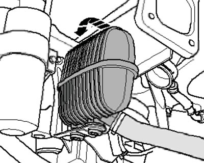
40.8. Resonator on a bracket
9. On CVT models, place under the connections (2 and 3 in Illustration 17.9) ATF collection pan, disassemble the connections and disconnect the ATF line brackets (1) from the engine.
10. Clamp the hoses near the power steering fluid radiator using clamps No.3094 (see illustration 5.9), place a tray under the hose connection and disconnect the hoses.
11. Remove the plugs, give away the nuts (see illustration) and remove the top engine cover, if necessary, remove the dipstick to measure the oil level. If present, remove the sound insulation located under the top cover.
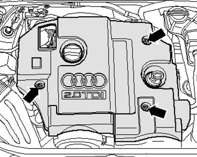
40.11. Fastening the upper engine cover
12. Remove the bolts (arrows in illustration 17.11) and remove the air ducts (1 and 2).
13. Remove the upper hose from the radiator (1 in illustration 5.14) engine cooling system, disconnect the connectors (2) of the left and right frontal impact sensors on the radiator frame.
14. Disconnect the electrical wiring connectors of both headlights (see illustration 5.15).
15. Perform the actions described in paragraphs 14-16 Section 17 and paragraphs 17-20 Section 5.
16. Remove the cooling system hoses (1, 3 in illustration 5.23), unscrew the expansion tank mounting screw (arrow) and move it to the side. Disconnect the K/L low coolant level sensor connector on the bottom of the expansion tank.
17. Remove the return hose from the fuel filter (2 in the illustration) and the feed hose (1).
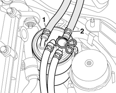
40.17. Hoses on the fuel filter
18. Disconnect the connector (1 in the illustration), release the fuel hoses on the air duct, unscrew the bolt (2) and remove the air duct (arrows).
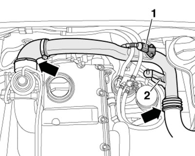
40.18. Removing the air duct
19. Remove the air duct from the intercooler (see illustration).
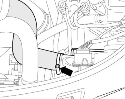
40.19. Hose on the intercooler
20. Place a tray underneath to collect the coolant, disconnect the coolant hose from the oil cooler (see illustration) and drain the remaining coolant.
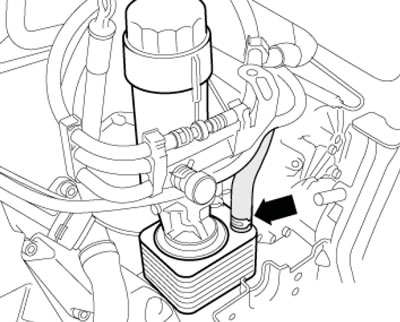
40.20. Coolant hose on oil cooler
21. Remove the hose from the branch pipe (arrow in illustration 5.31), going to the air conditioning system radiator.
22. Disconnect the coolant hose from the thermostat pipe (see illustration 29.15).
23. Mark the alternator belt with chalk or a felt-tip pen to indicate the direction of rotation so that you can install the belt in the same way. Loosen the belt tension by turning the tensioner in the direction of the arrow (see illustration), and secure the tensioner with tool No. T10060A. Remove the belt from the generator pulley.
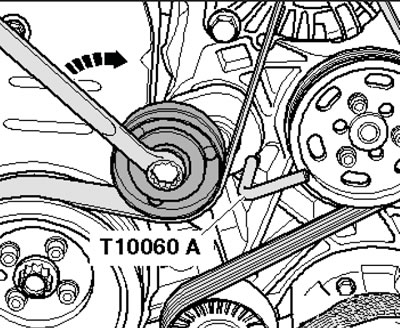
40.23. Removing the alternator belt
24. Unscrew the power steering pump pulley mounting bolts and remove the pulley (see illustration).
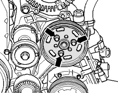
40.24. Fastening the power steering pump pulley
25. Remove the power steering pump fasteners (see illustration), remove it and tie it to the side without disconnecting the power steering lines.
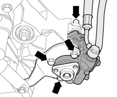
40.25. Power steering pump mounting
26. Disconnect the connector (1 in illustration 17.33) air flow meter and remove the air duct by loosening the clamp (2). Release the wiring harness on the air cleaner housing and remove the housing (arrows).
27. Remove the coolant hose from the EGR radiator (see illustration).
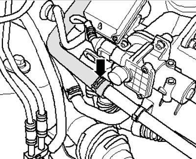
40.27. Coolant hose on EGR radiator
28. Disconnect the vacuum hose going to the brake booster from the front wall (see illustration).
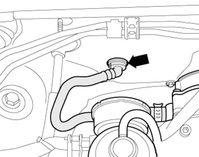
40.28. Brake booster vacuum hose
29. Unscrew the upper nuts (2 and 3 in the illustration) turbocharger/diesel particulate filter, loosen the lower fastening nut (1) a few turns to prevent the diesel particulate filter from falling out.
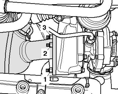
40.29. Turbocharger fastening
30. Remove the connector (2 in the illustration) temperature sensor in front of the diesel particulate filter from the bracket, disconnect the connector and release the wiring. Disconnect the connector of the exhaust gas pressure sensor No.1 (1), loosen the nut and remove the sensor from the bracket. Put the exhaust gas pressure sensor No.1 aside together with the connected hoses.
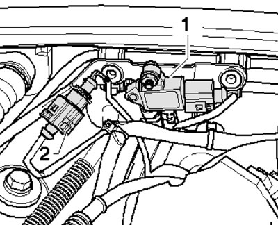
40.30. Connectors of the exhaust gas pressure sensor and the exhaust gas temperature sensor before the diesel particulate filter
31. Unscrew the fastener (arrow on the illustration) ground wires, remove the connectors (1-4) from the left bracket on the bulkhead, disconnect the connector (4) of the lambda probe and put the wiring down.
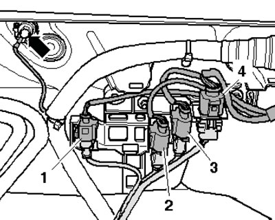
40.31. Bulkhead connectors
32. Remove the rubber seal (2 in the illustration) cover of the water drainage box (1) and remove the cover of the water drainage box.
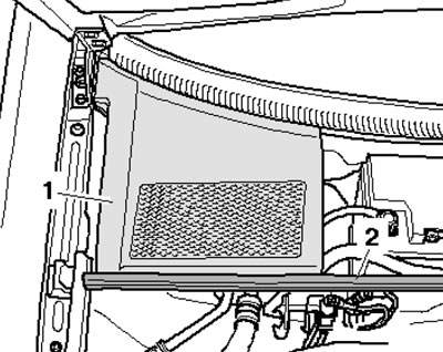
40.32. Cover of the water-draining box
33. Use a screwdriver to pry up and remove both protective caps (3 in illustration 5.32), loosen the nuts (4) a few turns and loosen the wiper arms (2), slightly rocking the axle. Loosen the nuts (4) completely and remove the wiper arms, then remove the safety clip (1) and the fairing grille (5) of the windshield.
34. Remove the cover of the mounting block in the water drainage box (see illustration 5.33).
35. Using a screwdriver, carefully remove the bracket (see illustration 5.34) and remove the ECM from the mounting block without disconnecting the electrical wiring from the ECM.
36. Press the locking hooks (see illustration) and remove the support bracket.
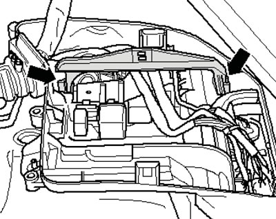
40.36. Removing the support bracket
37. Disconnect the lower electrical wiring connector (2 in illustration 5.37) and disconnect the wire (1), put the wiring harness aside.
38. Unlock the latches (see illustration 5.38) and remove the additional relay bracket from the mounting block in an upward direction. Disconnect the engine wiring harness from the mounting block and the engine compartment bulkhead, and lay it loosely on the engine together with the ECM. Secure the ECM so that it does not fall out.
39. Remove the transmission-to-engine mounting bolts (4-6 in illustration 5.64b), which are accessible from above. Remember the installation locations of bolts of different lengths, do not unscrew the bolt (5).
40. Give away the fasteners (1 in the illustration) refrigerant line bracket and separate it from the bracket (2).
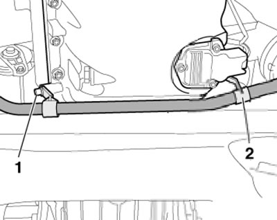
40.40. Fastening the refrigerant line
41. Disconnect the left engine mount connector (see illustration).
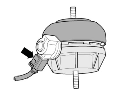
40.41. Left engine mount connector
42. Disconnect the engine oil level and temperature sensor connector (see illustration 5.47).
43. Disconnect the connector (1 in illustration 5.49) the wiring of the electromagnetic clutch of the air conditioning system compressor, unscrew the bolts (arrows) securing the compressor to the bracket and hang the compressor on the body without disconnecting the refrigerant lines from it.
44. Remove the air duct from the turbocharger by slightly lifting the mounting bracket (see illustration).
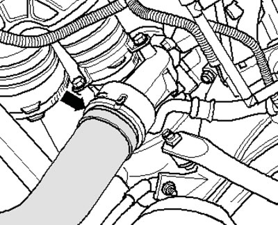
40.44. Turbocharger hose
45. Loosen the ground wire fastener on the right engine mount (see illustration).
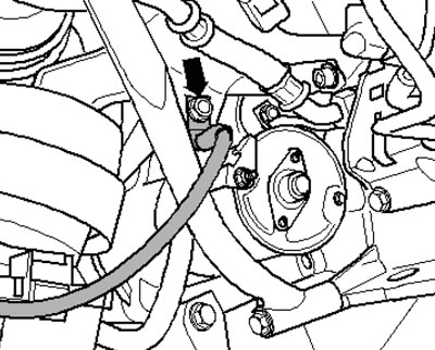
40.45. Ground wire on the right engine support
46. Remove the sound insulation in the right front wheel arch (see illustration).
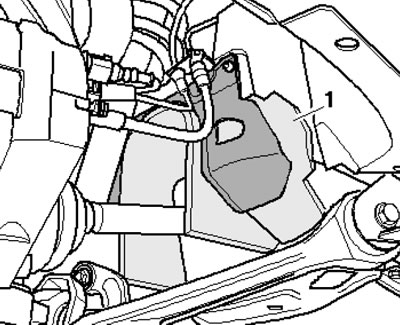
40.46. Sound insulation in the right wheel arch
47. Remove the heat shield (1 in illustration 5.43) of the inner CV joint of the right drive shaft.
48. Unscrew the threaded connections (1 in the illustration) and remove the front bracket of the inlet pipe.
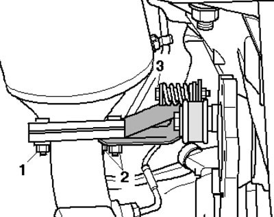
40.48. Fastening the front bracket of the inlet pipe
49. Unscrew the temperature sensor after the particulate filter (2 in the illustration), unscrew the bolt (1) and tilt the rear bracket of the exhaust pipe.
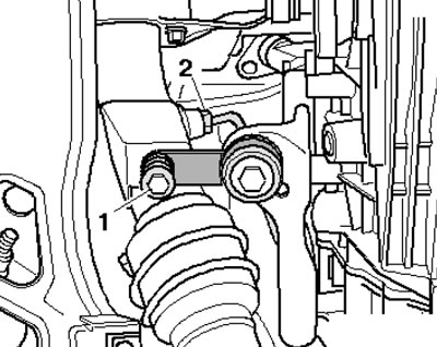
40.49. Fastening the rear bracket of the inlet pipe
50. Loosen the clamping sleeve mounting nuts (see illustration 5.42), move the clamp back and remove the intake pipe.
Caution: Do not bend the flexible section more than 10°.
51. Loosen the fastening nut by hand (1 in illustration 40.29) turbocharger/diesel particulate filter, remove the diesel particulate filter.
52. On models with a 6-speed manual transmission, disconnect the D/W reversing light connector and set the wiring aside (see illustration).
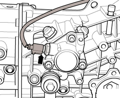
40.52. Reverse light wiring connector
53. Remove the transmission-to-engine mounting bolts (1, 3, 7-11 in illustration 5.64b), which are accessible from below. Remember the installation locations of bolts of different lengths.
54. Give the nut (1 in the illustration 17.40) clamp, disconnect the connector (3), remove the nut (2) and remove the electrical wiring, then remove the starter.
55. Mark the mounting position of the connections (1 in the illustration) and fixing bushings (2) at the bottom on the right and left engine support cushions.
Note: Different engines have different mounting holes. Loosen the nuts (1) from the bottom of the left and right mounts.
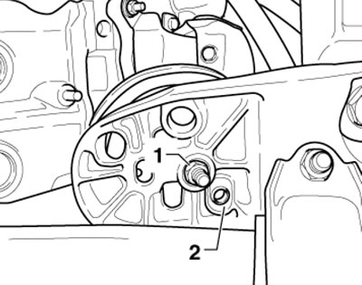
40.55. Engine mount fasteners
56. Loosen the top nut completely (see illustration 5.53) on the left engine mount, loosen the upper nut on the right mount a few turns. Remove the upper bolts of the engine-transmission connection flange, leaving one bolt screwed in by hand.
57. Install crossmember #10-222A on the connecting edges of the wings (the lead screws are located in the front) and secure the mounting fixture for #3147 into the bolt holes on the left and right side of the transmission dome as shown in the illustration 5.54. Connect conductor #3147 and crossmember #10-222A with hooks #10-222A/2 and slightly lift the engine using the crossmember lead screws.
Note: For better presentation, the engine is not shown in the illustration.
58. Attach the lifting device to the engine lifting eyes (see illustration), remove the last bolt securing the transmission to the engine. Make sure all hoses and wiring between the engine and the body are disconnected.
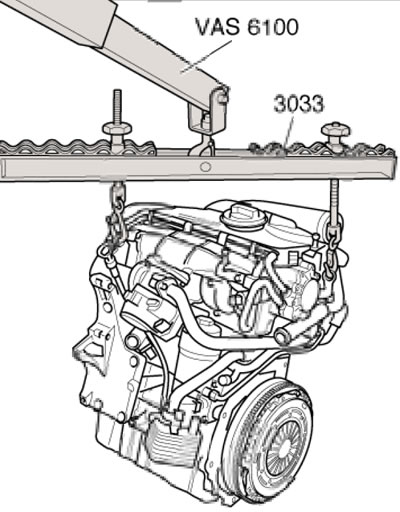
40.58. Fastening the lifting device to the engine
59. Raise the engine so that the threaded pins of the engine mounts are released, remove the left engine mount and tighten the lead screws of the crossmember No.10-222A.
60. Without damaging any engine compartment components, separate the engine from the transmission and move the engine forward out of the engine compartment.
61. Installation is carried out in the reverse order of dismantling the components. In doing so, please keep in mind the information provided in paragraphs 47-52 Section 17.