
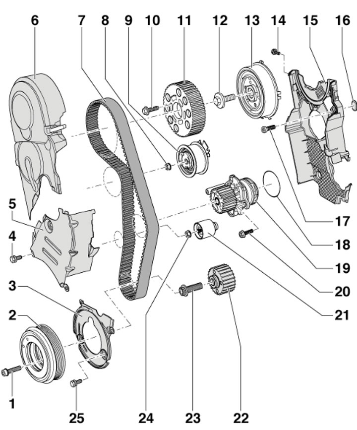
42.1. Timing Belt Installation Details 1. Crankshaft pulley mounting bolts, 10 Nm, then tighten to an angle of 90°, subject to replacement; 2. Crankshaft pulley; 3. Lower timing belt cover; 4. Cover fastening bolt 5; 5. Timing belt center cover; 6. Upper timing belt cover; 7. Timing belt; 8. Tensioner mounting nut 9, 20 Nm, then tighten to an angle of 90°; 9. Timing belt tensioner with roller; 10. Bolt for fastening the gear wheel 11, 25 Nm; 11. Camshaft gear wheel; 12. Hub mounting bolt 13, 100 Nm; 13. Hub with rotor of the SMR sensor; 14. Cover fastening bolt 15.10 Nm, installed on threaded varnish; 15. Rear timing belt cover; 16. Rubber plug; 17. Cover fastening bolt 15, 25 Nm; 18. Sealing ring, subject to replacement; 19. Water pump; 20. Pump mounting bolt 19, 15 Nm; 21. Intermediate roller; 22. Crankshaft gear; 23. Wheel mounting bolt 22, 120 Nm, then tighten to an angle of 90°, subject to replacement; 24. Roller fastening nut 21, 22 Nm; 25. Cover fastening bolt 3, 10 Nm, installed on threaded varnish
2. On models with independent/additional heating, remove the screw (1 in illustration 5.4) its exhaust pipe on a sound-insulating casing.
3. Unscrew the fasteners (1 and 2 in Illustration 5.5) and remove the front soundproofing screen. Remove the front bumper trim (see Chapter 11) and install the radiator frame in the service position (by analogy with Section 6).
4. Remove the plugs, give away the nuts (see illustration 40.11) and remove the top engine cover, if necessary, remove the dipstick to measure the oil level. If present, remove the sound insulation located under the top cover.
5. Release the clamps (arrows in illustration 41.6) and remove the upper timing belt cover.
6. Mark the alternator belt with chalk or a felt-tip pen to indicate the direction of rotation so that you can install the belt in the same way. Loosen the belt tension by turning the tensioner in the direction of the arrow (see illustration 40.23), and remove the belt from the generator pulley.
7. Remove the bolts (3 in the illustration) and remove the cover (2). Set the boost pressure limiting solenoid valve (1) with the connected hoses aside.
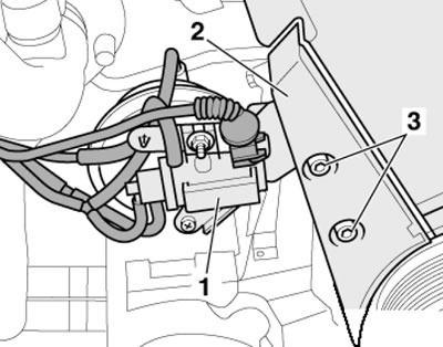
42.7. Removing the boost pressure control solenoid valve
8. Loosen the crankshaft pulley mounting bolts, holding the shaft from turning by the central bolt, and remove the pulley.
9. Give away the fasteners (see illustration) and remove the middle and lower timing belt covers.
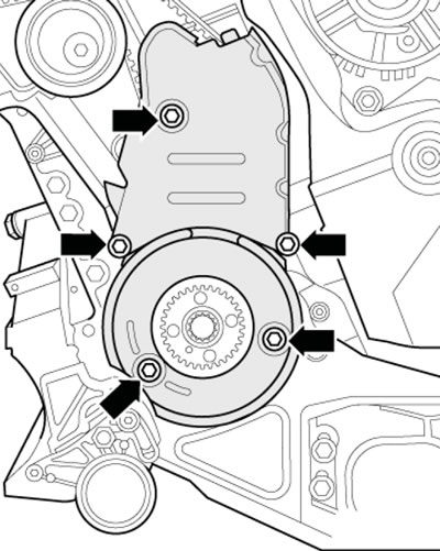
42.9. Fastening the middle and lower timing belt covers
10. Turn the crankshaft clockwise by the central bolt to the TDC position. In this case, the space between both protrusions (1 in the illustration) the rotor of the CMP sensor should be opposite the "4Z" mark (2) on the rear timing belt cover. Fix the toothed wheel using pin No.3359.
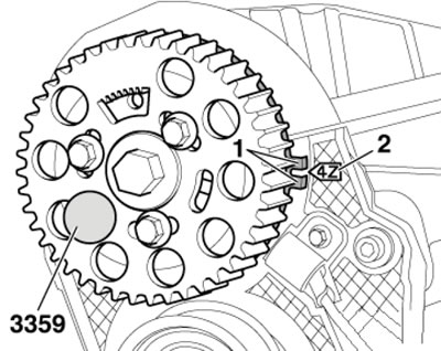
42.10. TDC position
11. Fix the crankshaft gear with tool No. T10100 (see illustration). The marks on the gear wheel (2) and the T10100 stopper (1) must be opposite each other, and the stopper journal must enter the hole in the seal holder.
Note: The stopper can only be pushed onto the gear wheel from the end face of the gear ring.
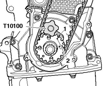
42.11. Fixing the crankshaft gear
12. Mark the direction of the timing belt with chalk or a felt-tip pen, loosen the three bolts (10 in illustration 42.1) camshaft gear fastenings.
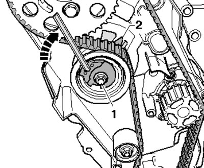
13. Loosen the fastening nut (1 illustration) tension roller. Turn the roller eccentric counterclockwise (arrow) so that the roller can be fixed with pin No. T10115. Screw in the free threaded pin, lubricated with thread varnish, until it stops.
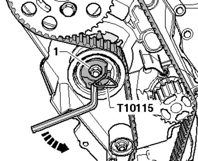
42.13. Fixing the tension roller
14. Turn the key clockwise until it stops (arrow on the illustration) and tighten the nut (1) completely. Remove the timing belt from the water pump and then from the remaining gears. The installation of the timing belt is described below, during which the timing phases are adjusted.
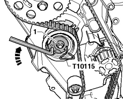
42.14. Removing the timing belt
15. Make sure that the camshaft is secured with pin #3359, the crankshaft is secured with stop #T10100, and the tension roller is secured with pin #T10115 and the fastening nut turned all the way to the right. Make sure that the engine is cold and none of the pistons are at TDC. Check that the tension roller is correctly installed in the rear timing belt cover (see illustration).
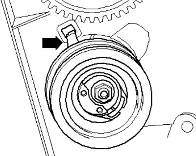
42.15. Correct position of the tension roller
16. Screw in the camshaft gear mounting bolts by hand so that it can rotate on the hub without tilting. Rotate the gear in the grooves clockwise until it stops and place the timing belt sequentially on: the camshaft gear, the tension roller, the crankshaft gear and the water pump gear.
17. Adjust the timing belt tension. To do this, remove the locking pin No. T10115, loosen the nut (1 in the illustration) and turn the tension roller eccentric clockwise with a rod wrench so that the pointer (2) is in the middle in front of the hole in the support plate.
42.17 Timing belt tension adjustment
Note: When loosening the fastening nut (1), make sure that the threaded pin does not come loose. Hold the tension roller in this position and tighten its nut with a force of 20 Nm, and then tighten the nut to an angle of 45°.
Note: Make sure that the nut does not turn together with the eccentric. When tightening the nut, the pointer turns a maximum of 5 mm to the right of the hole in the support plate - this position must not be changed, since the timing belt settles over time.
18. Install support No. T10172 with bolt No. T10172/4 as shown in the illustration and press in the direction of the arrow to maintain the pre-tension of the gear. Tighten the bolts (1) with a force of 25 Nm, remove locking pin No.3359 and crankshaft stopper No. T10100.
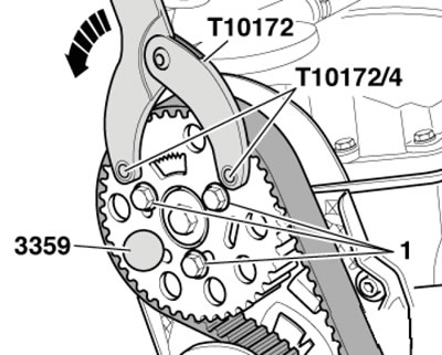
42.18. Tightening the camshaft gear fasteners
19. Turn the crankshaft two turns clockwise so that it is again in the TDC position and fix the hub from turning using pin No.3359 (see illustration 42.10). The space between the two protrusions (1) of the rotor must be opposite the "4Z" mark (2).
20. Check that the crankshaft can be locked with stopper No. T10100 and that the tension roller pointer is in the middle or maximum 5 mm to the right of the hole in the support plate. If the crankshaft cannot be locked, loosen the camshaft gear mounting bolts, turn the crankshaft slightly and lock it with stopper No. T10100.
Note: If the crankshaft has been rotated past TDC, first turn it back slightly and then re-set it to TDC.
21. Tighten the camshaft gear mounting bolts, remove locking pin No.3359 and stopper No. T10100. Check the correct installation of the timing phases by performing the actions described in paragraphs 19-20.
22. Further installation is carried out in the reverse order of dismantling the components.