
Table of contents: Setting the crankshaft to TDC ↓ Removal and installation the timing… ↓
1. Timing belt installation details are shown in the illustrations.
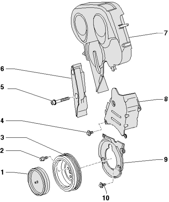
46.1a. Timing Belt Covers 1. Pulley plug 3; 2. Pulley mounting bolt 3, 10 Nm, then tighten to an angle of 90°, subject to replacement; 3. Crankshaft pulley; 4. Cover fastening bolt 8, 10 Nm, installed on threaded varnish; 5. Screen mounting bolt 6, 40 Nm; 6. Soundproof screen; 7. Upper timing belt cover; 8/9. Timing Belt Middle/Lower Cover; 10. Cover fastening bolt 9
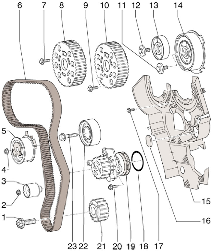
46.1b. Timing Belt Installation Details 1. Wheel mounting bolt 21, 120 Nm, then tighten to an angle of 90°, subject to replacement; 2. Roller fastening nut 3, 20 Nm; 3. Intermediate roller; 4. Roller fastening nut 5, 20 Nm, then tighten to an angle of 45°; 5. Tension roller; 6. Timing belt; 7/9. Wheel mounting bolt 8/10, 25 Nm; 8/10. Exhaust/intake camshaft gear; 11/12. Hub mounting bolt 13/14, 100 Nm; 13/14. Hub of exhaust/intake camshaft; 15. Back cover of belt 6; 16. Plug; 17. Cover fastening bolt 15, 10 Nm; 18. Sealing ring. To be replaced; 19. Water pump; 20. Pump mounting bolt 19, 15 Nm; 21. Crankshaft gear; 22. Intermediate roller; 23. Roller mounting bolt 22, 40 Nm, then tighten to an angle of 90°, subject to replacement
Setting the crankshaft to TDC
2. Bring the radiator frame to the service position (by analogy with Section 6).
3. Remove the alternator drive belt (see Section 41) and unload its tension element
4. Remove the upper timing belt cover by releasing its fasteners (7 in illustration 46.1a).
5. Remove the plug (1 in illustration 46.1a) crankshaft pulley and unscrew the pulley mounting bolts, holding the crankshaft from turning by the central bolt. Remove the pulley.
6. Unscrew the bolts securing the middle and lower timing belt covers and remove the covers (8 and 9 in illustration 46.1a).
7. Turn the crankshaft clockwise by the central bolt until the crankshaft gear can be secured with tool No. T10050 (for engines with round gear) or No. T10100 (for oval gear motors), - see illustration 44.1. In this case, the mark on the gear wheel should be located with the mark on the device (arrow), and the journal of the device should enter the hole in the front oil seal holder.
Note: The device can only be pushed onto the gear wheel from the end side of the splines.
Removal and installation the timing belt
8. Set the crankshaft to TDC position (see subsection above), remove the upper engine cover from the retainers (see illustration).
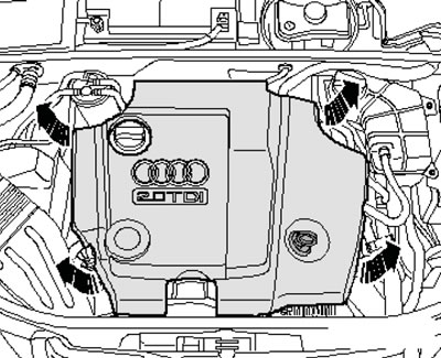
46.8. Upper engine casing fasteners
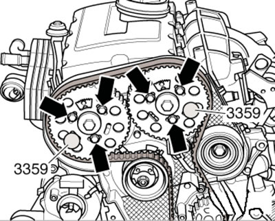
9. If the TDC position is set correctly, both toothed segments (arrows in the illustration) facing upwards. Secure the hubs with two #3359 locking pins.
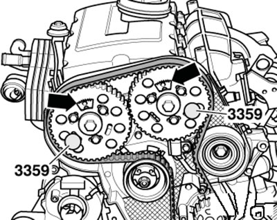
46.9. Fixing the camshaft hubs
10. Mark the direction of the timing belt movement with chalk or a felt-tip pen, loosen the three camshaft gear mounting bolts by two turns (arrows in the illustration).
46.10. Gear mounting bolts
11. Loosen the nut (1 in the illustration) tension roller fastenings and turn the roller eccentric with key No. T10020 counterclockwise so that the roller can be fixed with pin No. T 10115. Screw in the pin, lubricated with thread varnish, until it stops.
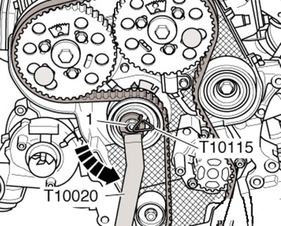
46.11. Fixing the timing belt tensioner
12. Turn key No. T10020 clockwise until it stops and tighten the nut by hand (1 in the illustration). Remove the timing belt from the water pump and then from the remaining gears.
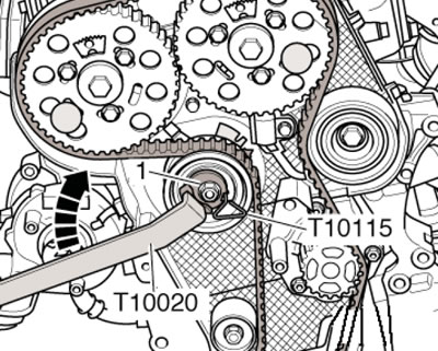
46.12. Timing belt tension loosening
13. Make sure that the camshafts are locked with stoppers No.3359 (see illustration 46.10). the crankshaft is secured with device No. T10050 or No. T10100, and the tension roller is secured with pin No. T10115 and a fastening nut.
14. Make sure that the tension roller is correctly positioned in the rear timing belt cover (see illustration 42.15).
15. Do not screw the bolts in completely (see illustration 46.10) fastenings of the camshaft gears so that they barely turn on the hubs without skewing. Turn the camshaft gears in the longitudinal grooves clockwise until they stop. Place the timing belt on the crankshaft, tension roller, camshaft gears, intermediate roller and, last of all, on the water pump gear.
16. Adjust the timing belt tension. To do this, remove pin No. T10115, loosen the nut (1 in the illustration) tension roller (while doing this, be careful not to release the pin) and turn the roller eccentric with key No. T10020 clockwise so that the pointer (2) is in the middle in front of the hole in the lower part of the crankcase. Holding the roller in this position, tighten its fastening nut, making sure that it does not turn together with the eccentric.
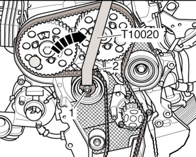
46.16. Tensioning the timing belt
Note: When tightening the nut, the pointer turns a maximum of 5 mm to the right of the hole in the lower part of the engine crankcase. This position should not be changed, as the timing belt will settle over time.
17. Maintain the timing belt pre-tension using key No. T10172 (see illustration), tighten the bolts securing both camshaft gears. Remove the camshaft stoppers and the crankshaft holding device.
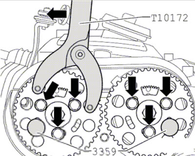
46.17. Tightening the fasteners of the camshaft gears
18. Rotate the crankshaft 2 revolutions until it is again at TDC. Lock the exhaust shaft hub with stopper #3359 and make sure of the following. The intake shaft hub and crankshaft must be secured with the above devices, and the tension roller pointer must be in the center or maximum 5 mm to the right of the hole in the lower part of the engine crankcase.
19. If the specified intake shaft hub is not locked, loosen the intake shaft gear mounting bolts and turn the intake shaft hub by the central bolt so that stopper No.3359 can be installed. Then tighten the fasteners and remove the crankshaft and camshaft locking devices.
20. Repeat the steps in paragraphs 18-19. If the crankshaft cannot be locked, loosen the camshaft gear mounting bolts and turn the crankshaft until it can be locked. Then tighten the fasteners and remove the crankshaft and camshaft locking tools.
21. Repeat the steps described in paragraphs 18-20.
22. Further installation is carried out in the reverse order of dismantling the components.