
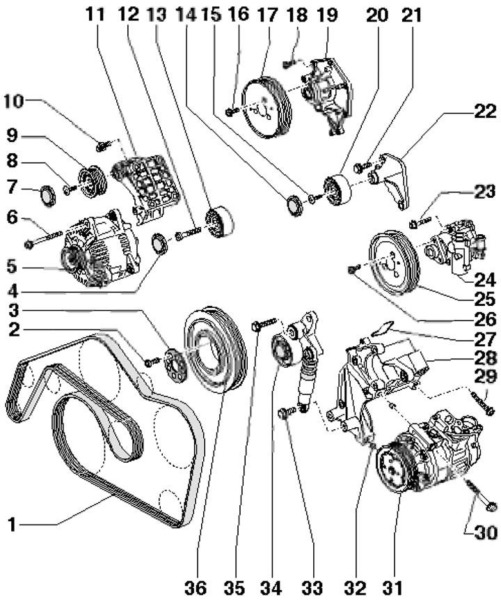
49.1. Generator Drive Belt Installation Details 1. Generator belt; 2. Pulley mounting bolt 36; 3. Compensating washer, subject to replacement; 4. Roller plug 13; 5. Generator; 6. Generator mounting bolt, 25 Nm; 7. Roller plug 9; 8. Roller mounting bolt 9.23 Nm; 9. Intermediate roller; 10. Bracket mounting bolt 11, 40 Nm; 11. Generator and roller bracket 9; 12. Roller mounting bolt 13, 23 Nm; 13. Intermediate roller; 14. Roller plug 20; 15. Roller mounting bolt 20, 23 Nm; 16. Pulley mounting bolt 17, 23 Nm; 17. Pump pulley 19; 18. Pump mounting bolt 19.9 Nm; 19. Water pump; 20. Intermediate roller (only on new models); 21. Roller mounting bolt 20, 23 Nm; 22. Roller bracket 20; 23. Pump mounting bolt 24, 23 Nm; 24. Vane pump; 25. Pump pulley 24; 26. Pulley mounting bolt 25, 22 Nm; 27. Gasket, subject to replacement; 28. Auxiliary units bracket; 29. Bracket mounting bolt 28, 40 Nm; 30. Compressor mounting bolt 31, 25 Nm; 31. Air conditioning compressor; 32. Centering bushings; 33. Tensioner mounting bolt 34, 23 Nm; 34. Belt tensioner 1; 35. Tensioner mounting bolt 34, 50 Nm, then tighten to an angle of 90°, subject to replacement; 36. Crankshaft pulley
2. The vacuum pump installation details are shown in the illustration.
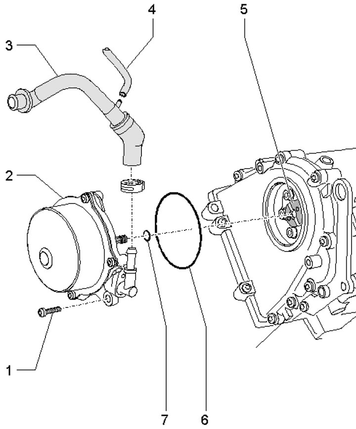
49.2. Vacuum pump installation details 1. Pump mounting bolt 2.9 Nm; 2. Vacuum pump; 3. Vacuum hose to the brake booster; 4. Vacuum hose; 5. Intake camshaft; 6, 7. Sealing ring, subject to replacement
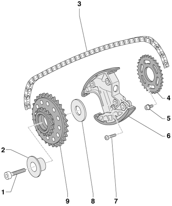
3. The timing chain drive parts are shown in the illustrations.
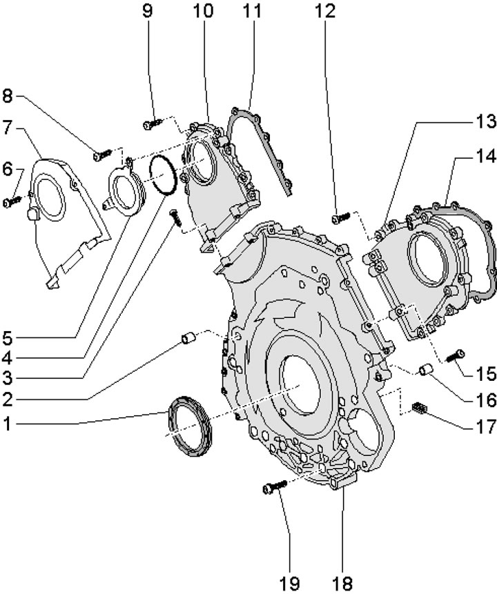
49.3a. Timing chain cover installation details 1. Front crankshaft oil seal; 2. Centering sleeve; 3, 9. Cover fastening bolt 10, 8 Nm, then tighten to an angle of 90°, subject to replacement; 4. Sealing ring, subject to replacement; 5. Lid; 6. Shield mounting bolt 7.9 Nm; 7. Thermal shield; 8. Cover fastening bolt 5.9 Nm; 10/13. Timing chain cover left/right; 11/14. Cover gasket 10/13; 12, 15. Cover fastening bolt 13, 8 Nm, then tighten to an angle of 90°°, subject to replacement; 16. Centering sleeve; 17. Compaction; 18. Lower timing chain cover; 19. Cover fastening bolt 18
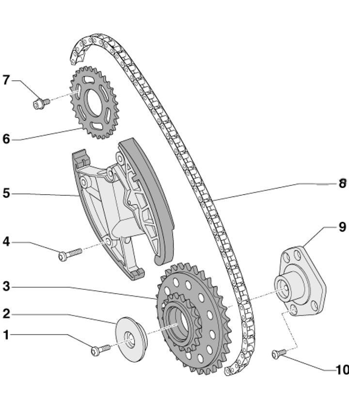
49.3b. Timing chain of the left cylinder head 1. Sprocket mounting bolt 3.5 Nm, then tighten to an angle of 90°, subject to replacement; 2. Sprocket adjusting washer 3; 3. Chain drive sprocket 8; 4. Tensioner mounting bolt 53.5 Nm, then tighten to an angle of 90°, subject to replacement; 5. Chain tensioner 8; 6. Camshaft drive sprocket; 7. Sprocket mounting bolt 6, 23 Nm; 8. Timing chain of the left cylinder head; 9. Sprocket bracket 3; 10. Bracket mounting bolt 9.9 Nm
49.3s. Timing chain of the right cylinder head 1. Sprocket mounting bolt 9, 45 Nm; 2. Sprocket bushing 9; 3. Timing chain of the right cylinder head; 4. Camshaft drive sprockets; 5. Sprocket mounting bolt 4, 23 Nm; 6. Chain tensioner 3; 7. Tensioner mounting bolt 6.5 Nm, then tighten to an angle of 90°, subject to replacement; 8. Sprocket adjusting washer 9; 9. Chain drive sprocket 3
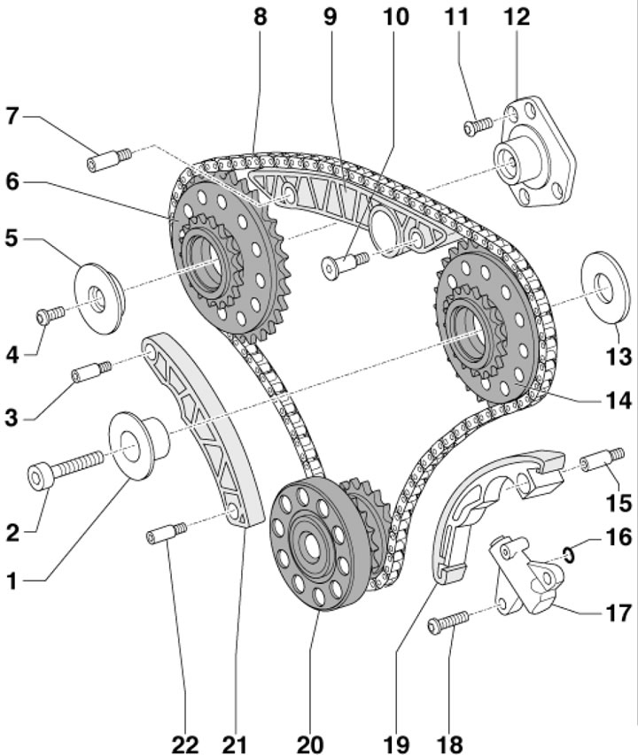
49.3d. Lower timing chain 1. Sprocket bushing 14; 2. Sprocket mounting bolt 14, 45 Nm; 3, 7. Axle, 12 Nm; 4. Sprocket mounting bolt 6.5 Nm, then tighten to an angle of 90°, subject to replacement; 5. Sprocket bushing 6; 6. Left timing chain drive sprocket; 8. Lower timing chain; 9. Chain guide bar 8; 10. Awn, 12 Nm; 11. Bracket mounting bolt 12.9 Nm; 12. Sprocket bracket 6; 13. Adjusting washer; 14. Right timing chain drive sprocket; 15. Axle, 12 Nm; 16. Sealing ring, subject to replacement; 17. Chain tensioner 8; 18. Tensioner mounting bolt 17, 12 Nm; 19. Chain tensioner bar 8; 20. Crankshaft; 21. Chain guide bar 8; 22. Axle, 9 Nm
4. The drive parts of the oil pump and balance shaft are shown in the illustration.
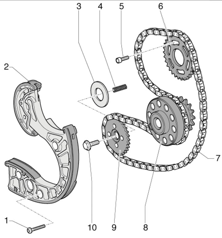
49.4. Oil pump and balance shaft drive parts 1. Tensioner mounting bolt 2.9 Nm; 2. Chain tensioner 7; 3. Adjusting washer; 4. Pressure spring; 5. Sprocket mounting bolt 6, 23 Nm; 6. Balance shaft sprocket; 7. Oil pump and balance shaft drive chain; 8. Crankshaft; 9. Oil pump sprocket; 10. Sprocket mounting bolt 9, 62 Nm
5. The details of the installation of the cylinder head and its cover are shown in the illustrations.
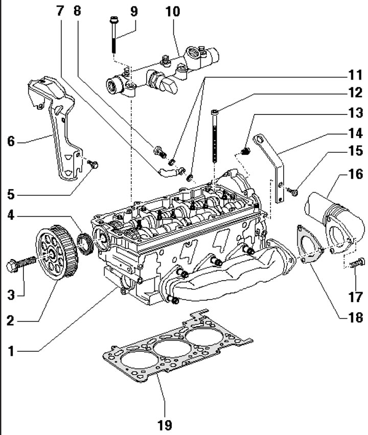
49.5a. Cylinder head installation details (using the example of the left bank of cylinders) 1. Cylinder head; 2. Driving gear; 3. Wheel mounting bolt 2, 75 Nm; 4. Wheel sealing ring 2, subject to replacement; 5. Bracket mounting bolt 6.9 Nm; 6. Inlet manifold bracket; 7. Cooling system pipe; 8. Hollow bolt, 15.5 Nm; 9. Bolt for fastening the main line 10, 23 Nm; 10. Fuel distribution line; 11. Sealing ring, subject to replacement; 12. Cylinder head mounting bolt, subject to replacement; 13. Pressure limiting valve (except new models),25 Nm; 14. Lifting eye; 15. Bolt for fastening eye 14 (M6 - 9 Nm, M8 - 23 Nm); 16. Intermediate pipe on the left; 17. Pipe mounting bolt 16, 30 Nm, then tighten to an angle of 90°; 18. Laying pipe 16; 19. Cylinder head gasket
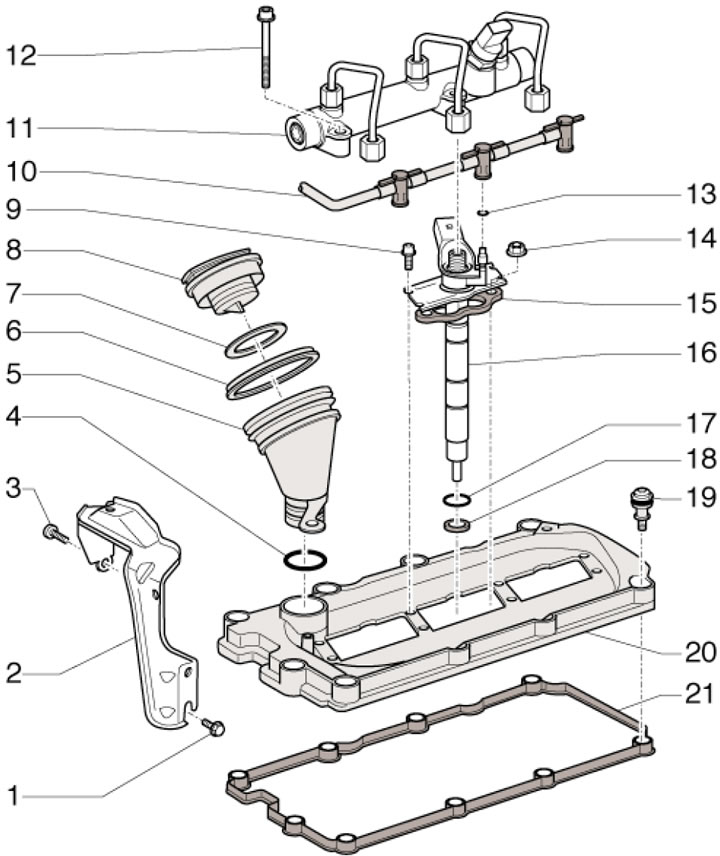
49.5b Cylinder Head Cover Installation Details (using the example of the left bank of cylinders) 1, 3. Bracket mounting bolt 2, 9 Nm; 2. Inlet manifold bracket; 4. Sealing ring, subject to replacement; 5. Oil filler neck; 6, 7. Sealing ring; 8. Neck cover 5; 9. Injector mounting bolt 16.5 Nm; 10. Return fuel line; 11. Fuel distribution line; 12. Bolt for fastening the main line 11, 23 Nm; 13. Sealing ring, subject to replacement; 14. Injector mounting nut 16, 9 Nm; 15. Catch (replaced when replacing the injector); 16. Nozzle; 17. Sealing ring; 18. Copper sealing ring; 19. Special cover mounting bolt 20.9 Nm; 20. Cylinder head cover; 21. Cover gasket 20
6. The details of the gas distribution mechanism are shown in the illustration.
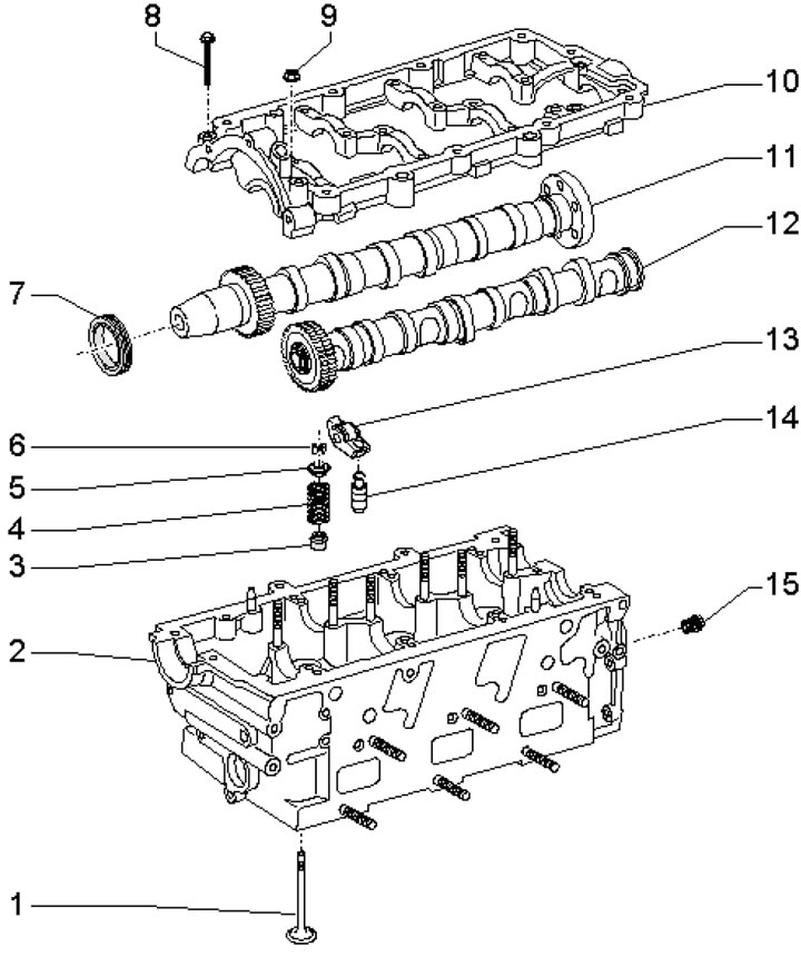
49.6. Timing belt parts 1. Valve; 2. Cylinder head; 3. Oil deflector cap; 4. Valve springs; 5. Spring plate 4; 6. Split valve lock crackers; 7. Camshaft oil seal, subject to replacement 8/9 Cover mounting bolt/nut 10.9 Nm; 10. Camshaft cover; 11/12. Inlet/outlet camshaft; 13. Rocker; 14. Hydraulic compensator; 15. Pressure limiting valve, 25 Nm
7. The installation details of the engine lubrication system components are shown in the illustration.
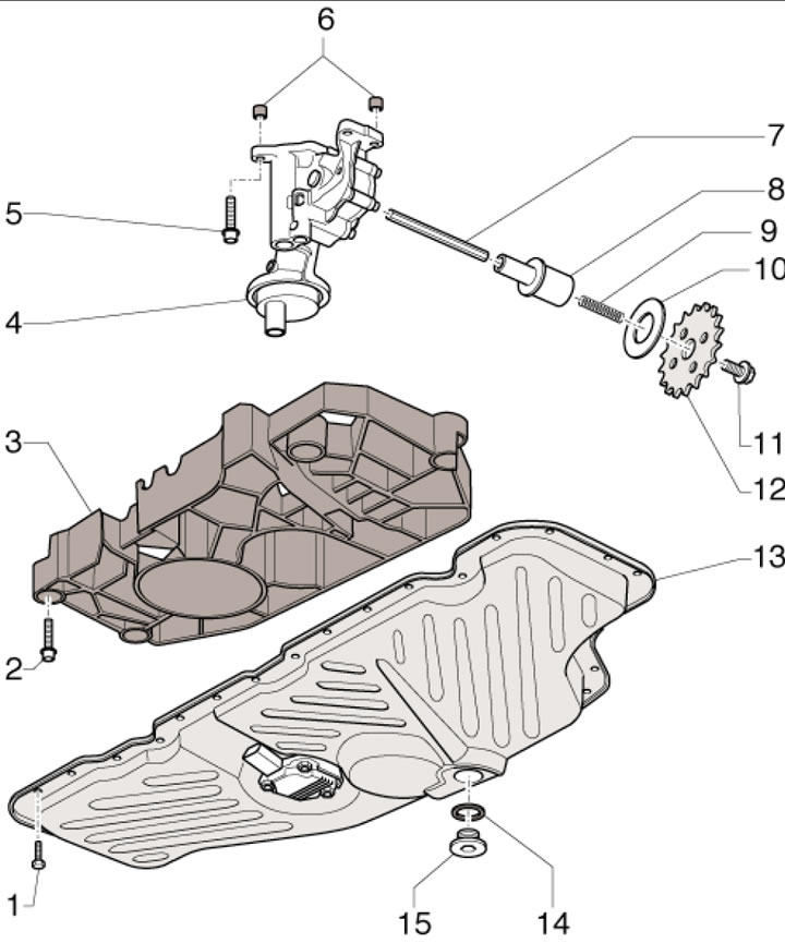
49.7a. Oil pump and lower oil pan installation details 1. Oil pan mounting bolt 13.8 Nm, then tighten to an angle of 90°, subject to replacement; 2. Self-locking bolt of oil separator mounting 3.8 Nm, then tighten to 90° angle, subject to replacement; 3. Oil separator; 4. Oil pump with 11 bar pressure reducing valve and 3.5 bar pressure regulating valve; 5. Pump mounting bolt 4, 23 Nm; 6. Centering bushings; 7. Oil pump drive shaft; 8. Leash; 9. Pressure spring; 10. Adjusting washer; 11. Sprocket mounting bolt 12, 64 Nm; 12. Oil pump sprocket; 13. Oil pan (lower section); 14. Sealing ring, subject to replacement; 15. Drain plug
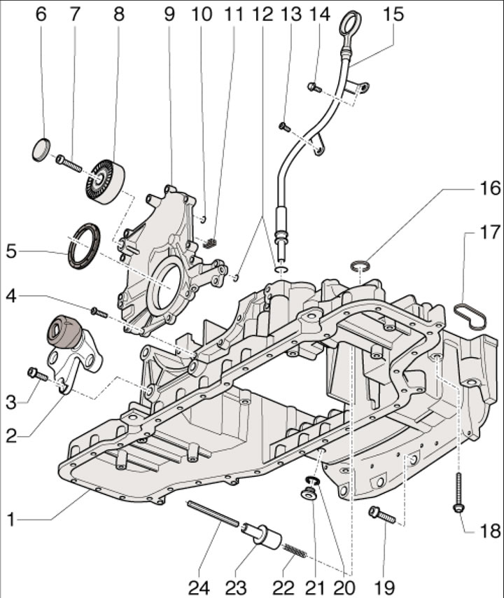
49.7b. Upper Oil Pan Section Installation Details 1. Oil pan (upper section); 2. Engine mount; 3. Support mounting bolt 2, 40 Nm; 4. Holder mounting bolt 9.9 Nm; 5. Front crankshaft oil seal; 6. Lid; 7. Roller mounting bolt 8, 23 Nm; 8. Intermediate roller of the alternator belt; 9. Front crankshaft oil seal holder; 10, 12. Sealing ring, subject to replacement; 11. Compaction; 13/14. Tube mounting bolts 15, 15/45 Nm; 15. Feeler gauge guide tube; 16, 17. Gasket, subject to replacement; 18/19. Oil pan mounting bolt 1, 15 /45 Nm; 20. Sealing ring, subject to replacement; 21. TDC fixing hole plug; 22. Pressure spring; 23. Leash; 24. Oil pump drive shaft
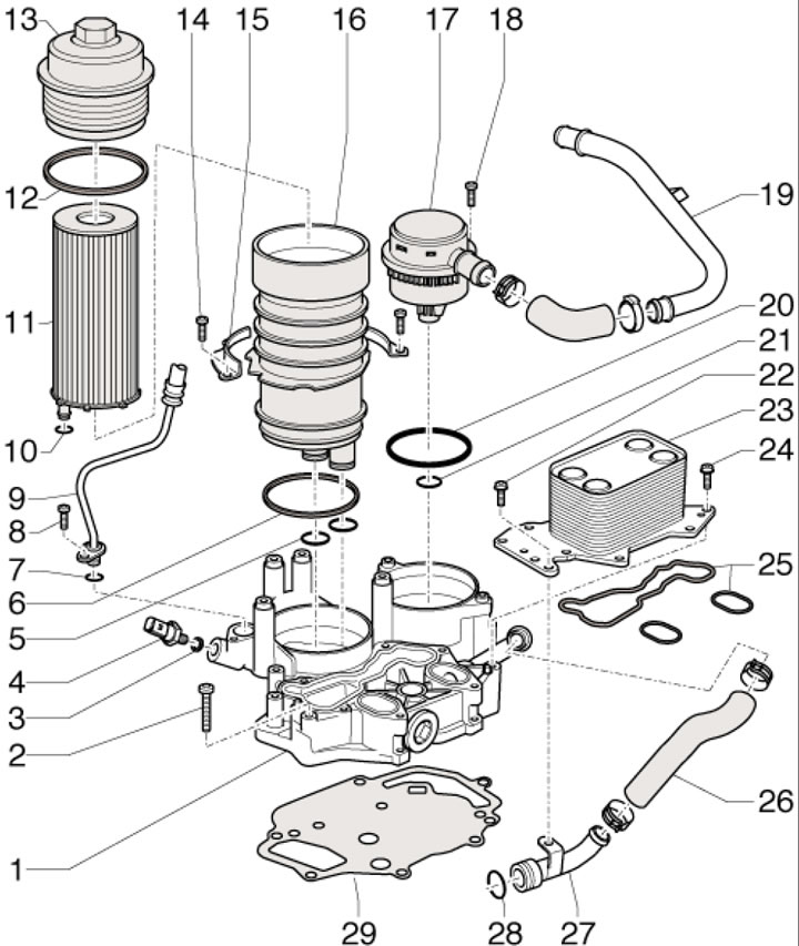
49.7c. Oil cooler, pressure reducing valve and oil filter installation details 1. Foundation; 2. Base mounting bolt 1.9 Nm; 3. Sealing ring, subject to replacement; 4. D/V oil pressure at 0.9 bar, 20 Nm; 5, 7. Sealing ring, subject to replacement; 6. Gasket, subject to replacement; 8. Oil line mounting bolt 9.9 Nm; 9. Oil supply line; 10. Sealing ring, subject to replacement; 11. Filter element; 12. Gasket, subject to replacement; 13. Cover, 35 Nm; 14. Bolt, 9 Nm; 15. Oil filter mounting bracket; 16. Oil filter housing with a bypass valve for 2-3 bar; 17. PCV valve; 18. Valve mounting bolt 17.9 Nm; 19. PCV tube; 20, 21. Sealing ring, subject to replacement; 22, 24. Oil cooler mounting bolt 23, 9 Nm; 23. Oil cooler; 25. Gaskets subject to replacement; 26. Coolant hose; 27. Front coolant supply pipe; 28. Sealing ring, subject to replacement; 29. Gasket, subject to replacement
(Read the original source on the website: AUDIMANUAL.ru)