
Repair Chevrolet Repair Toyota Repair Honda Repair AvtoVAZ Repair Mercedes-Benz Repair BMW Repair Opel
Home  |  Contacts  |  Sitemap  |    
English Русский
Български
Беларускі
Український
Српски
Hrvatski
Română
Polski
Slovenský
Magyar
AudiManual.ru


  • AUDI 80
  • AUDI 100
  • AUDI A3
  • AUDI A4
  • AUDI A6
  • AUDI A8
  • AUDI Q
  • OTHER
  • ARTICLES
B8 (2007-2015) B7 (2004-2008) B6 (2000-2006) B6 (2000-2006, petrol) B5 (1994-2001) B5 (1994-2001, petrol)

Cylinder head and its components (2.0L TDI-PD (DOHC)) (Audi A4 B7)

  • Home
  • Audi A4
  • B7 (2004-2008)
  • Power unit
  • Diesel engines
  • Cylinder head and its components (2.0L TDI-PD (DOHC))
            0
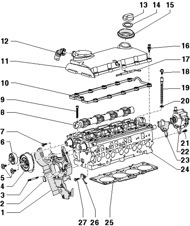
1. The cylinder head installation details are shown in the illustration.

47.1. Cylinder head installation details 1. Rear timing belt cover; 2. Rubber plug; 3. Hairpin, 15…

47.1. Cylinder head installation details 1. Rear timing belt cover; 2. Rubber plug; 3. Hairpin, 15 Nm; 4. Intake shaft hub with CMP sensor rotor; 5. Hub mounting bolts 4 and 6, 100 Nm; 6. Exhaust shaft hub with CMP sensor rotor; 7. Cover fastening bolt 1, 10 Nm, installed on threaded varnish; 8. Rocker arm axle; 9. Rocker arm bolt, subject to replacement; 10. Cover gasket 11; 11. Head cover 24; 12. PCV hose; 13. Filler plug; 14. Gasket; 15. Plug; 16. Special cover mounting bolt 11, 10 Nm; 17. Vacuum hose; 18. Bolt, 20 Nm; 19. Head mounting bolt 24, subject to replacement; 20. Washer; 21. Pump mounting bolt 22, 20 Nm; 22. Twin pump; 23. Pump gasket 22, subject to replacement; 24. Cylinder head; 25. Head gasket 24; 26. SMR sensor; 27. Sensor mounting bolt 26, 10 Nm, installed on threaded varnish


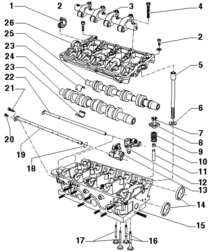
2. The installation details of the camshafts and valves are shown in the illustration.
47.2. Timing belt parts 1. Pipe bracket, 10 Nm; 2. Cover fastening bolt 26, 20 Nm; 3. Rocker arm…

47.2. Timing belt parts 1. Pipe bracket, 10 Nm; 2. Cover fastening bolt 26, 20 Nm; 3. Rocker arm axle; 4. Axle bolt 3, needs to be replaced; 5. Head mounting bolt 15, subject to replacement; 6. Bolt washer 5; 7. Split valve lock crackers; 8. Spring plate 9; 9. Valve spring; 10. Oil deflector cap; 11. Valve guide bushing; 12/13. Inlet/outlet side rocker arm with pressed-in hydraulic compensator; 14. Sealing rings, subject to replacement; 15. Cylinder head; 16/17. Inlet/outlet valves; 18. Sealing ring; 19.22. Rocker axis; 20,21. Bolt, 10 Nm; 23. Bearing insert; 24/25. Exhaust/intake camshaft; 26. Camshaft cover


Removal and installation camshafts


3. Bring the radiator frame to the service position (by analogy with Section 6).

4. Remove the upper engine cover from the retainers (see illustration 46.8).

5. Disconnect the vacuum line (3 in the illustration).
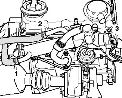
47.5. Vacuum pipe (3) and water hoses (1 and 2)

47.5. Vacuum pipe (3) and water hoses (1 and 2)


Note: Do not disconnect the water hoses.


6. Remove the bolts (1 in the illustration) and nuts (2). Unscrew the bolts (arrows), remove the EGR radiator and set it aside with the cooling system hoses connected.
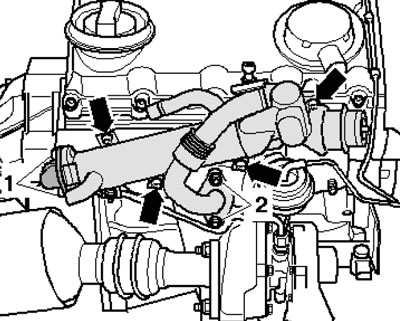
47.6. Removing the EGR cooler

47.6. Removing the EGR cooler


7. Remove the bolts and the EGR cooler bracket from the cylinder head. Remove the timing belt (see Section 46).
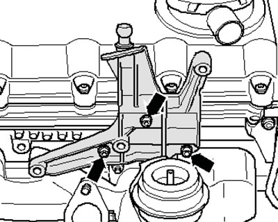
47.7. EGR radiator bracket fastener

47.7. EGR radiator bracket fastener


8. Remove the camshaft stoppers No.3359 and unscrew the bolts securing their gears (see illustration 46.10). Remove the gear wheels.

9. Loosen the bolts (1 in the illustration) fastening the hubs of both camshafts by approximately two turns, using counter support No. T10051.
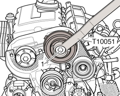
47.9. Unscrewing the hub bolt (using the example of the intake shaft)

47.9. Unscrewing the hub bolt (using the example of the intake shaft)


10. Alternately apply puller No. T10052 to the hub of each camshaft and screw the bolts into the hub (arrows in the illustration). Remove the hub by holding the hex key of the puller and screwing in the bolt.
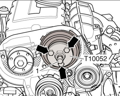
47.10. Removing the hub (using the example of the intake shaft)

47.10. Removing the hub (using the example of the intake shaft)


11. Remove the bolts (2 and 4 in the illustration).
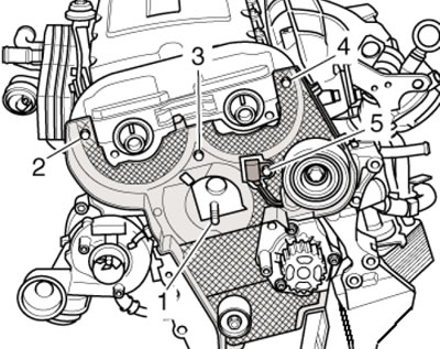
47.11. Timing Belt Rear Cover Fastening Bolts

47.11. Timing Belt Rear Cover Fastening Bolts


Note: Do not remove bolts 1, 3 and 5.


12. Remove the PCV hose and vacuum hose from the cylinder head cover (arrows in the illustration). Loosen the cylinder head cover bolts in sequence from 11 to 1 and remove it.
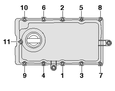
47.12. Cylinder head cover fastener tightening sequence

47.12. Cylinder head cover fastener tightening sequence


13. Loosen the locknuts (2 in the illustration) adjusting bolts (1) on all unit injector units and unscrew the adjusting bolts so that the corresponding rocker arm is pressed against the unit injector pusher spring.
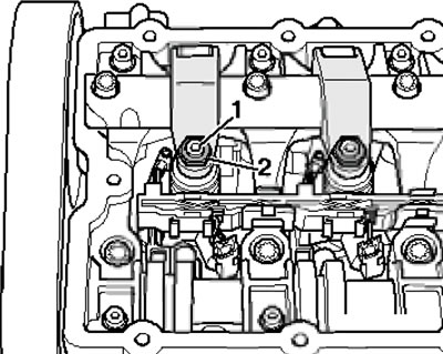
47.13. Unscrewing the adjusting bolts

47.13. Unscrewing the adjusting bolts


14. Remove the bolts (1, 3 and 5 in the illustration). Loosen and remove bolts (2 and 4) in several stages. Remove the rocker shaft and dual pump.
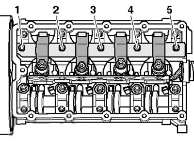
47.14. Removing the rocker arm shaft

47.14. Removing the rocker arm shaft


Note: To ensure that individual components remain secured to the shaft, do not remove the rocker arm shaft bolts; if necessary, mark the position of the bolts on the rocker arm.


15. Remove the pin (1 in the illustration) and remove the knurled nut (2). Disconnect the central connector of the pump-injectors and glow plugs.
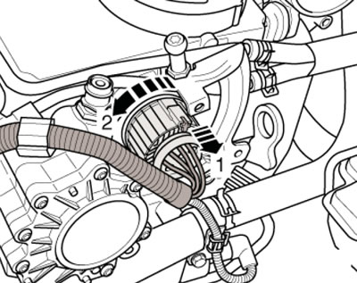
47.15. Pump-injector connector

47.15. Pump-injector connector


16. Disconnect the glow plug connectors (And in the illustration) and pump-injector modules (B). Unscrew the screws (arrows) on the fasteners and set the wiring harness as a set aside.
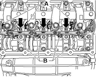
47.16. Glow plug and pump-injector connectors

47.16. Glow plug and pump-injector connectors


17. Loosen the remaining 15 camshaft cover bolts evenly, moving from the edge inward (see illustration).
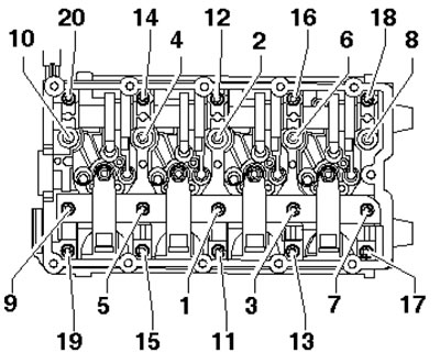
47.17. Support module fastening bolts

47.17. Support module fastening bolts


18. Turn the bolts SW15 of frame No. T10262 counterclockwise by hand until they stop. Install the frame on the camshaft cover as shown in the illustration and tighten the bolts SW10 with a torque of 10 Nm. Turn the release bolts SW15 by hand clockwise until they rest against the cylinder head bolts, then evenly turn the release bolts in the sequence indicated on the bolt heads until the camshaft covers are separated from the cylinder head. Remove the camshaft cover and camshafts.
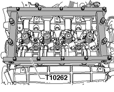
47.18. Removing the camshaft cover

47.18. Removing the camshaft cover


19. Remove any remaining sealant from the bearing module and cylinder head, clean the mounting surfaces from oil and grease. Make sure the crankshaft is in the TDC position.

20. Lubricate the camshaft grooves with engine oil and set the shafts in the TDC position (see illustration): on both shafts, the cams (1 and 2) of cylinder No.1, as well as the grooves (arrows) must be facing upwards.
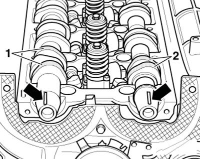
47.20. Position of camshafts at TDC

47.20. Position of camshafts at TDC


21. Apply a 2mm thick bead of sealant to the clean mounting surface of the support module (arrows in the illustration).
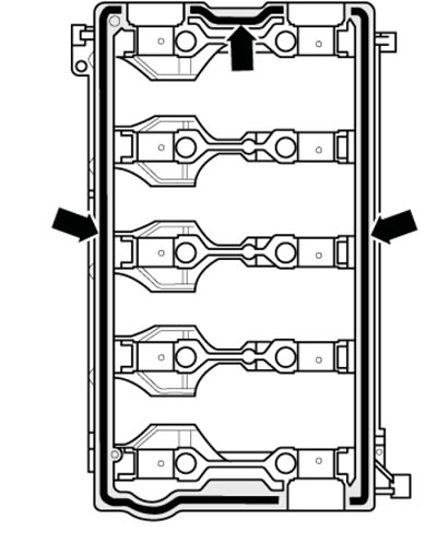
47.21. Places of sealant application

47.21. Places of sealant application


22. Tighten the bolts evenly (1-20 see illustration 47.17), moving from the center to the edge. Bolts (1, 3, 5, 7 and 9) pull to a 90° angle.

23. Further installation is carried out in the reverse order of dismantling the components.
The article was checked by auto expert Timur Bazhenov
This article is available at russian, bulgarian, belarusian, ukrainian, serbian, croatian, romanian, polish, slovak, hungarian

Share information:
Previous articles
Audi A4 B7: Diesel engines
Next articles

Timing Belt Replacement, TDC Setting (2.0L TDI-PD (DOHC))
Lubrication system (1.9 and 2.0 l TDI-PD (SOHC))
Cylinder head and its components (1.9 and 2.0 l TDI-PD (SOHC))
Flywheel, crankshaft and pistons (1.9 and 2.0L TDI-PD (SOHC))
Lubrication system (2.0L TDI-PD (DOHC))
Features of engine design (2.7 and 3.0 l)


Similar articles on other Audi car models:
Cylinder head — removal and installation Audi 80 B3 (1986-1991, petrol)
Checking the cylinder head components Audi 100 C4 (1990-1994)
Removal and installation the cylinder head (petrol) Audi A3 Type 8L (1996-2003)
Cylinder head — 1.8-I engine (125/150 hp) Audi A6 C5 (1997-2004)
Left cylinder head cover Audi A8 D2 (1994-2002)
Cylinder head Audi Q5 Type 8R (2008-2017)
Cylinder head — design description Audi A2 (1999-2005)
Link to this page in different formats


Visitor comments

No comments yet


How much will 28 + 43 =


A4(B8, 2007-2015) 
  • General information
  • Operating instructions
  • Power unit
  • Petrol engines 1.8 l
  • Petrol engines 1.8/2.0 l
  • Petrol engines 3.0 l
  • Petrol engines 3.2 l
  • Fuel system (petrol)
  • Diesel engines 2.0 l (CA*)
  • Diesel engines 2.0 l (CJCB)
  • Diesel engines 2.7/3.0 l
  • Diesel engines 3.0 l
  • Fuel system (diesel)
  • Transmission
  • Manual gearbox 0B1
  • Manual gearbox 0B2
  • Manual gearbox 0B3
  • Manual gearbox 0B4
  • Automatic transmission 0B5
  • Automatic transmission 0B6
  • Automatic transmission 0AW
  • All-wheel drive system
  • Chassis
  • Front suspension
  • Rear suspension
  • Brake system
  • Steering system
  • Body
  • Exterior
  • Interior
  • Seats
  • Doors, locks and windows
  • Security system
  • Heating and air conditioning
  • Electrical equipment
  • Audio system
  • Power devices
  • Equipment and devices
  • Lighting and lamps
  • Electrical circuits
 
A4(B7, 2004-2008) 
  • General information
  • Introduction to manual
  • Troubleshooting
  • Operating instructions
  • Maintenance
  • Power unit
  • Petrol engines 2.0 (ALT)
  • Petrol engines 2.0 (TFSI)
  • Petrol engines 1.8 (MPI)
  • Diesel engines
  • Cooling system
  • Air conditioner
  • Fuel and exhaust system
  • Ignition system
  • Starting and charging
  • Transmission
  • Clutch
  • Manual gearbox
  • Automatic gearbox
  • Drive shafts
  • Chassis
  • Brake system
  • Front suspension
  • Rear suspension
  • Steering
  • Body
  • Exterior
  • Interior
  • Electrical equipment
  • Equipment and devices
  • Lighting and signaling
  • Windscreen wipers and washers
  • Electrical diagrams
  • Electrical diagrams (since 2007)
 
A4(B6, 2000-2006) 
  • General information
  • Vehicle Description
  • User manual
  • Maintenance
  • Power unit
  • Gasoline engine
  • Diesel engine
  • Lubrication system
  • Cooling system
  • Supply system
  • Injection system
  • Exhaust system
  • Ignition and control
  • Transmission
  • Gear box
  • Clutch and drive shafts
  • Chassis
  • Brake system
  • Car suspension
  • Steering
  • Body
  • Heating and ventilation
  • Exterior (external elements)
  • Interior (internal elements)
  • Electrical equipment
  • Power devices
  • Lighting and appliances
  • Electrical circuits
 
A4(B6, 2000-2006, petrol) 
  • General information
  • Introduction to the guide
  • Car care
  • Power unit
  • Engine repair
  • Lubrication system
  • Cooling system
  • Injection and control system
  • Ignition system
  • Power and exhaust system
  • Transmission
  • Clutch and drive shafts
  • Car gearbox
  • Chassis
  • Suspension and wheels
  • Steering
  • Brake system
  • Body
  • Interior
  • Exterior
  • Electrical equipment
  • Equipment and devices
  • Lighting and signaling
  • Power devices
  • Electrical circuits
 
A4(B5, 1994-2001) 
  • General information
  • Introduction to the guide
  • Car care
  • Maintenance (gasoline)
  • Maintenance (diesel)
  • Power unit
  • Gasoline engines
  • Diesel engines
  • Engine overhaul
  • Cooling system
  • Fuel injection (gasoline)
  • Fuel system (diesel)
  • Exhaust system
  • Ignition system
  • Transmission
  • Clutch
  • Mechanical gearbox
  • Automatic gearbox
  • Drive shafts
  • Chassis
  • Brake system
  • Car suspension
  • Steering
  • Body
  • Exterior
  • Interior
  • Doors, locks and windows
  • Heating and ventilation
  • Electrical equipment
  • Power devices
  • Equipment and devices
  • Electrical circuits
 
A4(B5, 1994-2001, petrol) 
  • General information
  • Vehicle description
  • Maintenance
  • Power unit
  • Engine repair
  • Turbocharging
  • Exhaust system
  • Cooling system
  • Ignition system
  • Fuel system
  • Motronic injection system
  • MPI and MPFI injection system
  • Transmission
  • Clutch
  • Gearbox and shafts
  • Chassis
  • Steering
  • Car suspension
  • Brake system
  • Wheels and tires
  • Body
  • Heating and ventilation
  • Body parts
  • Electrical equipment
  • Fuses and relays
  • Power devices
  • Lighting and lamps
  • Tools and devices
  • Electrical circuits
 
AudiManual.ru © 2017-2026 · Mobile version · Feedback · Sitemap: EN BG BY UA RS HR RO PL SK HU · Site search · News and articles
80 B2 · 80 B3 petrol · 80 B3 · 80 B4 · 100 C3 diesel · 100 C3 petrol · 100 C3 · 100 C4 petrol · 100 C4 · A3 Type 8L · A4 B5 petrol · A4 B5 · A4 B6 petrol · A4 B6 · A4 B7 · A4 B8 · A6 C4 · A6 C5 · A6 C5 Allroad · A8 D2 · Q5 Type 8R · Q7 Typ 4L · Audi A2 ·
This site uses cookies 🍪. Click the button to accept this fact.