
Table of contents: Valve springs ↓ Valve seats ↓ Valves ↓ Cylinder head ↓ Camshaft ↓ Cylinder head assembly ↓
Valve springs
A special device is required to check the valve springs correctly, although the exact lengths of the "stressed" springs are unknown. When using the device, it should be assumed that all springs have approximately the same elasticity. If there is no device for checking springs available:
Compare a used spring with a new spring. To do this, clamp both springs in the same vice and slowly tighten them. When both springs are compressed to the same value, this means that they have approximately the same tension. If the old spring allows compression to a shorter size than the new one, this means that the spring is tired and then they should be replaced as a set.
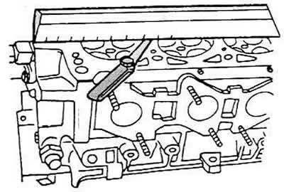
Place the springs in order on a flat surface (glass) so that the closed coil is at the bottom. Place a steel corner near the spring. Measure the gap between the spring and the corner at the top, it should not exceed 2.0 cm. Otherwise, the spring is bent.
Move the valve plate up and down and read the readings on the dial indicator. They should not exceed 1.0 mm for the intake valves and 1.3 mm for the exhaust valves of the engine.
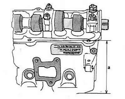
Check the general condition of the cylinder head before replacing the guide bush. A cylinder head with small scratches between the valve seats or between the valve seat and the first thread of the spark plug can be used after grinding if the scratches are no wider than 0.3 mm. The distance between the arrows (a) of the head after grinding should be 132.6 mm (four-cylinder engines).
When replacing a guide bushing, the old bushing should be pressed out of the cylinder head using a suitable punch (rod). The cylinder head can be heated to ensure operation. The punch used to remove the bushing should have a loaded pin that matches the size of the inside of the bushing.
New bushings should be well lubricated and pressed into the cold cylinder head from the camshaft side until the flange of the bushing touches the cylinder head. The force of the press should not exceed 1 ton, otherwise the flange can be cut off.
Guide bushings should be ground after pressing. It should be remembered that the inner diameters of bushings for different types of engines differ. An adjustable reamer can be used for grinding. Guide bushings for intake and exhaust valves are the same. Valve seats should be ground after replacing the bushings.
Valve seats
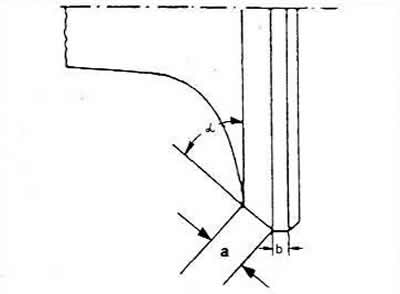
All valve seats should be checked for wear or grooves. Small traces of wear can be corrected with a 45° cutter. If the seat has become too wide, the seats should be reground. The angle to be obtained is shown in the first picture - for the inlet valve, in the second - for the outlet. It is necessary to pay attention to the difference in the diameters of the valve seats, which are indicated in "Technical specifications" for different engines. The seat sizes are different because the intake and exhaust valves themselves are not the same for different types of engines.
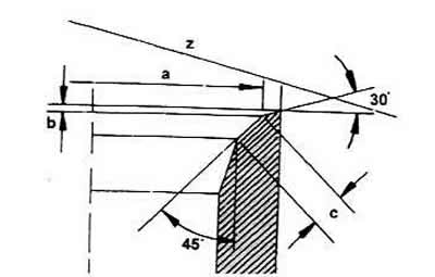
Intake Valve Seat Dimensions
a Valve seat diameter
b Maximum grinding value
with Valve seat width, 2D mm
z Cylinder head edge
30° Upper Angle
45° Valve Seat Angle
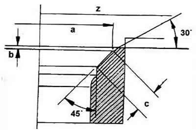
Exhaust valve seat dimensions
a Valve seat diameter
b Maximum grinding value
c Widened valve seats, 2.mm
z Cylinder head edge
30° Upper Angle
45° Valve Seat Angle
To determine if sanding is necessary, the following measurements should be taken:
Insert the valve into the guide bushing and press it firmly against the valve seat.
Measure the distance (a) between the tops of the valves and the top edge of the cylinder head.
Calculate the maximum allowable grinding value from the measured value and the allowable minimum value. For the intake valves, this value is 33.8 mm and 34.1 mm. The minimum distance for the exhaust valve is 33.0 mm.
If the minimum distance differs from the measured value, the maximum permissible grinding value must be taken, which is indicated in the figures above as (c). In this case, the following instructions must be observed:
The valve seats should be ground down when installing new guide bushings. In this case, proceed as follows:
Rout the 45° angle and then lightly mill the top edge of the seat with a 30° router to bring the seat width to the range shown in the table. Routing should be completed when the seat width is within the range shown.
To avoid the seat being seated too deeply in the cylinder head, the above measurement must be taken.
The ground valve seats need to be lapped. To do this, the valve seat surfaces need to be lubricated with some grinding paste and the corresponding valve installed in the corresponding seat. Attach a vacuum cleaner nozzle to the valve and move the valve back and forth.
After lapping, all parts must be thoroughly cleaned of dirt and grinding paste, and the valve seat on the valve plate and the chamfer must be checked. Both parts must show a continuous matte chamfer, which clearly indicates the width of the valve seat. The latter must be measured as follows:
Draw a few lines on the valve plate with a pencil. The lines should be approximately 1 mm apart around the circumference. Then carefully lower the valve into the guide bushing and seat, turn the valve 90°. Press down on the valve slightly.
Pull out the valve and check if the lines on the valve seat are worn. If the valve seat width is normal, the cylinder head can be reinstalled. Otherwise, the valve seats must be ground, and in the most severe cases, the cylinder head must be replaced.
Valves
Minor damage to the valve seat surface can be corrected by lapping the valve in the cylinder head seat as described above.
Measure the valves and replace all valves with those corresponding to the specified dimensions. Note that the dimensions differ for different engine types. The values are given in "Technical specifications".
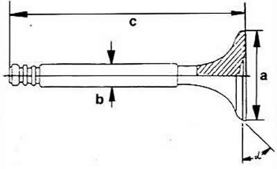
a Valve plate diameter
b Valve stem diameter
c Valve length.
If wear is found on the edges of the valve stem, it can be ground down using a grinder, but do not remove more than 0.5 mm of material.
Inlet valves can be ground, provided that the value (b) is not less than 0.5 mm. Grinding of exhaust valves is not allowed, since they are made of a special material. Exhaust valves can only be ground with paste or replaced.
a maximum: 3.5 mm
b minimum: 0.5 mm
α — 45°
Note: Old valves are useful as test valves. Sodium filled valves cannot be used for this purpose.
Cylinder head
Thoroughly clean the sealing surfaces of the cylinder head and check the cylinder head surface for warpage. To do this, apply a ruler to the head and use a flat feeler gauge to measure the gap in the longitudinal, transverse and diagonal directions relative to the head surface. If you can insert a flat feeler gauge thicker than 0.1 mm, then the cylinder head can be ground. If the gap is larger in any place, the cylinder head will have to be replaced. By measuring the cylinder head as described above, you can determine whether its size is sufficient to be ground.
Camshaft
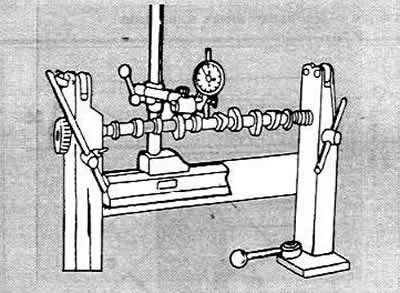
The camshafts of all 2-valve engines look the same, but the cams are positioned at different angles to ensure correct valve timing, i.e. to achieve timely opening and closing of the valves. Therefore, it is recommended that you take the old camshaft with you when buying a new camshaft. When ordering a camshaft, you should specify the model number of the car and the engine number. Before reinstalling the camshaft, you should thoroughly check it. First, place the camshaft between prisms or clamp it in the centers of a lathe, as shown in the figure, and attach a dial gauge to the journal of the middle bearing. Slowly turn the camshaft. read the readings of the gauge. If the readings exceed 0.01 mm, then the camshaft is bent and must be replaced.
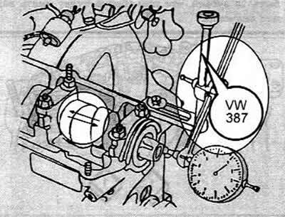
Check the bearing journals for visible damage. If there are grooves or other irregularities, the shaft should be replaced. To measure the axial clearance of the distribution hall, it must be placed in the cylinder head (without pushers) and secure with the front and rear bearing caps. Place the cylinder head on a flat surface. Attach the dial indicator to the end surface as shown in the figure and move the shaft in both directions. The clearance should not exceed 0.15 mm. Otherwise, the bearing cap support surface is worn out.
Cylinder head assembly
The cylinder head is assembled in the reverse order of disassembly.
The valve stems should be well lubricated with engine oil and installed in the appropriate bushings.
Using a special tool, place the lower plates of the valve springs opposite the valve guide bushings.
Install the valve stem seals. There is a special tool for this (10-204).
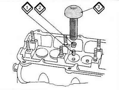
Push the plastic sleeve (1) of the device onto the protruding sleeve.
Lubricate the seal (2) well and place it on the plastic sleeve.
Place the device (3) on the seal and carefully press the seal onto the guide bushing. It should be borne in mind that when installing the seal without this device or a similar one, the seal can be damaged, which will result in increased oil consumption.
If the valves have been lapped, they must be installed in the corresponding seats, since each valve lapping is individual.
Install the appropriate inner and outer valve springs on the cylinder head (if the springs are reinstalled).
Hit the top of the valve stem with a plastic hammer. This will cause the incorrectly seated crackers to pop out. As a precaution, place a rag under the ends of the springs to prevent the parts from popping out.
Install the pushers in the holes according to the previously made marks (well oiled), if the old pushers are installed.
Lubricate the camshaft bearing journals well with oil.
Raise the camshaft in the bearings and turn it several times. Finally, turn the camshaft so that the valve cams of the first cylinder are facing upwards.
Install bearing caps #2 and #3 and tighten the nuts slightly. Since the caps have a special shape, you should check whether they are installed correctly. The figure shows the correct installation of the bearing caps.
Tighten the nuts of the installed bearing caps alternately crosswise by several turns until a tightening torque of 20 Nm is reached. Check that the surfaces of the caps are in contact with the surface of the cylinder head.
Install covers No.1 and No.3. Screw on the nuts and tighten them alternately crosswise to a torque of 20 Nm.
Take the camshaft oil seal in your hand and determine which side the spring is on. Turn the side with the spring inward and lightly lubricate the edge of the seal (and also the shaft surface). To install a new seal, use a piece of pipe of the appropriate diameter. The pipe should fit completely around the outer circumference of the seal. Install the seal and drive it in so that it is flush with the outer surface of the head. You can install the seal in the same way as described for the front crankshaft seal.
Place the camshaft drive gear on the shaft (don't forget the key and check that it is installed correctly) and tighten the bolt with the washer. Holding the gear in a suitable way (for example, using an old toothed belt), tighten the bolt to a torque of 8 Nm.
Install the remaining parts into the cylinder head, except for those that are installed when the head is installed.