
Table of contents: Portable (A) and stationary (B)… ↓ Mandrel for installing oil deflector… ↓ Gauge for measuring the depth of the… ↓ Device for grinding working chamfers… ↓ Device for dressing grinding wheels ↓ Device for processing working… ↓ Grinding machine for grinding… ↓ Mandrel for pressing out valve guide… ↓ Reamer kit for valve guide sleeve… ↓ Devices for testing engine valves… ↓ Device for hydraulic testing of… ↓ Sound indicator for determining the… ↓
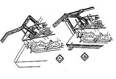
Portable (A) and stationary (B) device for mounting and dismounting engine valves
Using one of the devices, compress the valve springs, remove the released crackers, valve springs with plates and support washers. Turn the cylinder head and remove the valves from the bottom. Remove the oil-deflecting caps from the guide bushings. Install the valves in the reverse order.
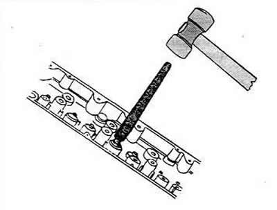
Mandrel for installing oil deflector caps on valve guide bushings
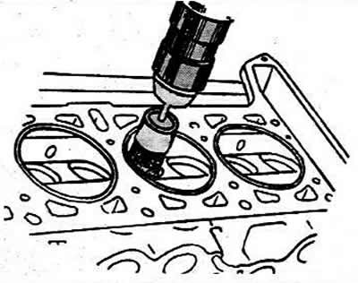
A metal brush driven by an electric drill — to remove carbon deposits from the combustion chambers of the cylinder head and from the surface of the exhaust valves.
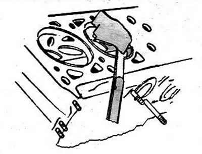
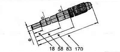
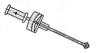
Gauge for measuring the depth of the combustion chamber of the cylinder head
This operation is performed as shown in the figure if the head has been ground as a result of deformation.
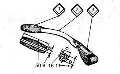
Device for grinding working chamfers of valve seats
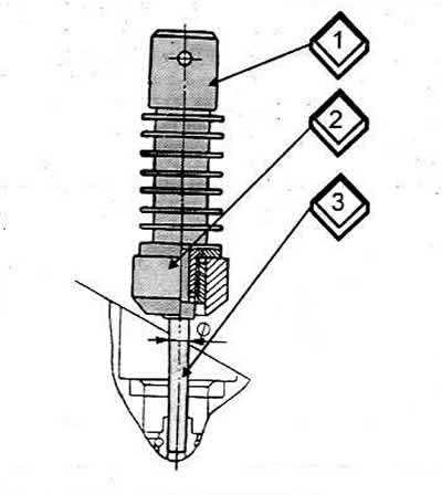
1 Spindle
2 Grinding wheel
3 Guide rod
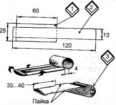
Device for dressing grinding wheels
Device for processing working chamfers of valve seats
1 Spindle
2 Cutters
3 Guide rod
Grinding machine for grinding working chamfers of valves
To do this, it is necessary to install a valve on the grinding machine and fix the movable support so as to obtain the required chamfer angle.
1 Valves
2 Grinding wheel
3 Lever
Mandrel for pressing out valve guide bushings and mandrels for pressing in these bushings
The clearance between the guide bushings and the valve stem is checked with a dial indicator or by measuring the diameter of the valve stem and the bore of the guide bushing.
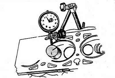
If it is not possible to ensure the required clearance when replacing the valve, it is necessary to replace the valve bushings with mandrels.
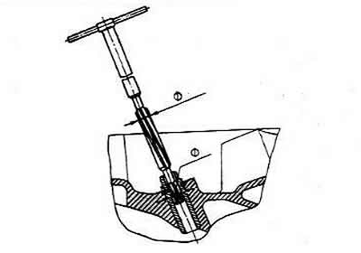
Reamer kit for valve guide sleeve holes
After pressing in the guide bushings, it is necessary to bring their diameters to the nominal dimensions using inlet and outlet valve reamers.
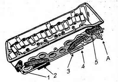
Devices for testing engine valves for leaks
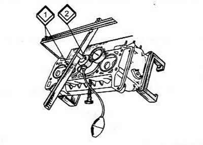
To do this, thoroughly clean the seats and valves and install the cylinder head on the support (3). Insert the valves into the corresponding guide bushings and close the spark plug holes with plugs (4). Set the device (2) to the position shown in the figure. Press the lever hard and pump air with a rubber bulb until the pressure gauge shows a pressure of 50 kPa. No pressure drop should be observed within 10 seconds. If the pressure drops, i.e. there is an air leak, then it is necessary to repeat the grinding of the working chamfer of the valve and the seat on the cylinder head.
Device for hydraulic testing of cylinder head cooling jacket tightness
And the water supply
1, 2, 3 Plugs
4 Plate
5 Flange with water supply nipple
To do this, install the parts included in the device kit on the head, connect the pump to the tap and feed water into the head under a pressure of 0.5 MPa. There should be no water leakage from the cylinder head within 2 minutes. If cracks are detected, the cylinder head must be replaced. The tightness of the cylinder head can also be checked with compressed air. To do this, instead of water, supply compressed air under a pressure of 0.15-0.2 MPa, lower the cylinder head into a bath of water heated to 60°-80°C, and warm it up for 5 minutes. There should be no air leakage from the head within 1-1.5 minutes.
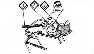
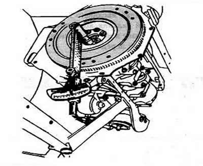
Torque wrench — for technologically correct tightening of fasteners.
Tightening the engine flywheel mounting bolts with a torque wrench is shown in the figure.
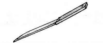
Probe— to check the clearance between the valve drive lever and the camshaft cam.
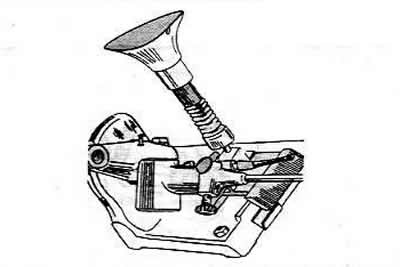
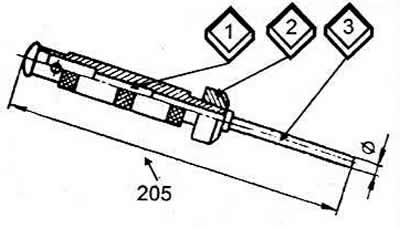
Sound indicator for determining the compression stroke in the engine cylinder
To install a distributor on the engine or to check and set the ignition timing using a test lamp, it is necessary to determine the compression stroke in the first cylinder. To do this, you need to unscrew the spark plug of the first cylinder, close the spark plug hole with a paper plug or a sound indicator plug, consisting of a wooden plug, a rubber hose and any whistle that you can make yourself, turn the crankshaft with the starting handle and by pushing the paper plug out of the spark plug socket or by the sound of the whistle determine the compression stroke in the cylinder.
1, 2 Plates
3 Plug
(The original source of the article can be found on the website: audimanual.ru)