
Table of contents: Piston ring sharpening tool ↓ Tools for pressing the piston pin… ↓ Device for testing the strength of… ↓ Device for checking the parallelism… ↓ Grinding machine and fixture for… ↓ Prisms for checking the geometric… ↓ Cutter and cutter mandrel for… ↓ Mandrel for pressing in new plugs ↓ Device for measuring the axial… ↓ Mandrel for installing the rear oil… ↓
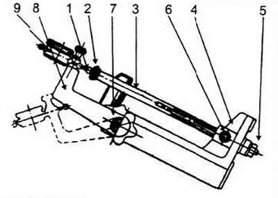
Traverse — for removing and installing the engine. To do this, hang a crossbar or a clamp on the hoist, grabbing the engine with hooks on the right side by the bracket installed on the front stud for fastening the exhaust manifold, and on the left by the technological hole made in the lug of the engine block, or by the bolt screwed into the threaded hole for fastening the clutch housing.
Stand— for disassembling and assembling the engine.
Bracket — for mounting the engine on the stand.
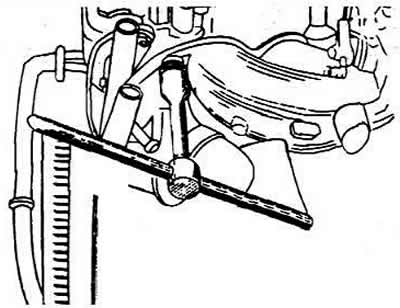
Key— for fastening the nuts of the intake and exhaust manifolds. The tightening torque of the nuts is 25 Nm. Unscrewing the nuts is shown in the figure.
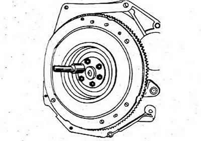
Fixator— to prevent the flywheel from turning. When unscrewing or screwing the crankshaft ratchet, clutch mounting bolts or flywheel, it is necessary to install a retainer in the hole in the block to secure the flywheel from turning.
Key— for loosening and tightening the central bolt of the crankshaft and turning the engine crankshaft when adjusting the valves.
Puller— to remove the front bearing of the gearbox primary shaft.
Keys— for unscrewing and screwing in studs.
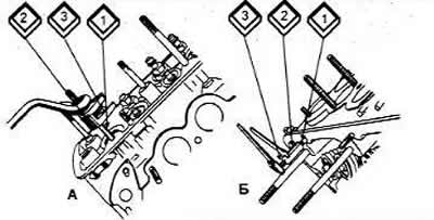
Using the key (A), the stud (1) is clamped in the hub (2) by the eccentric (3). In the key (B), the stud (1) is clamped in the nut (2) by the bolt (3). The diameter and thread pitch of the key must match the stud.
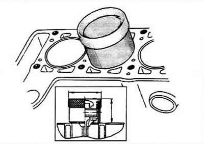
Set of bushings — for installing pistons together with piston rings and connecting rods into the engine block cylinders. When installing pistons, a bushing corresponding to the piston size is selected. The surfaces of the cylinders and pistons must be lubricated with engine oil before installation.
Mandrels— for pressing in the plugs of the crankshaft and cylinder block. The plugs are removed with a center punch and are performed during a major overhaul of the engine in order to thoroughly clean the cooling jacket of the cylinder block from scale and the oil channels of the cylinder block, crankshaft and camshaft from resinous deposits on their walls. After pressing in the plugs of the oil channels, they must be calked with a center punch at several points.
Ring gauges — to set the bore gauge to zero when measuring engine cylinder wear.
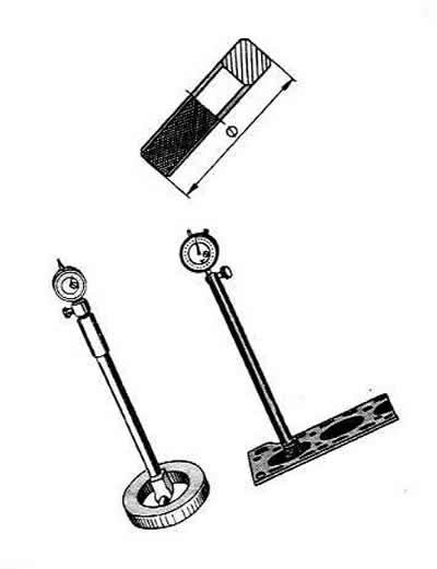
Nutrometer — to measure the wear of the engine block cylinders. The cylinder diameter is measured in four zones. In each zone, two measurements are taken — in the longitudinal and transverse directions of the engine. In the zone of zone (1), the cylinders are practically not worn. Therefore, by the difference in measurements in the first and other zones, it is possible to judge the amount of wear of the cylinders.
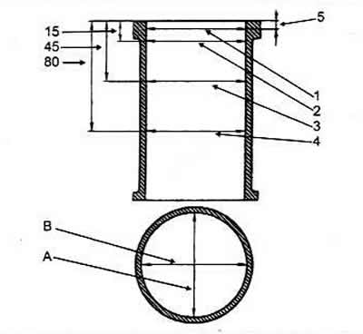
A, B. Direction of measurements
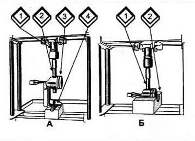
Boring machine— for boring the engine block cylinders to the oversize, honing machine — for final processing of the cylinders. Honing is performed first with a set of medium-grain abrasive bars, then with fine-grain ones. To achieve the best possible cleanliness of the cylinder working surface, it is finished with fine-grain sandpaper wound on the honing head. Mandrel and piston support — for pressing out the piston pin. The piston pin is pressed out on a press using mandrel 2 (A) and support (4) with a cylindrical recess into which the piston is placed, or using support 2 (B). Before pressing out the pin, the piston rings are removed.
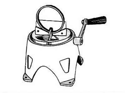
Piston ring sharpening tool
It is checked with a set of feeler gauges when installing rings in a gauge with a hole diameter equal to the nominal diameter of the ring, with a tolerance of ±0.003 mm.
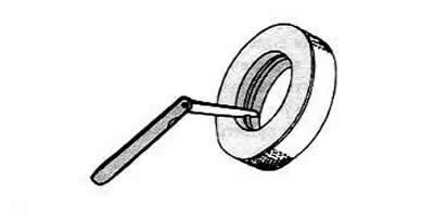
If the gap is insufficient, it is necessary to file the joint surfaces of the rings on a device, and if the gap is too large, the rings must be replaced.
Calibrated plastic wire — to check the clearance between the liners and the crankshaft journals of the engine. The clearance between the liners and the crankshaft journal can be checked by calculation (having measured the details). However, it is more convenient to use a calibrated plastic wire to check the clearance. In this case, it is necessary to thoroughly clean the working surfaces of the liners and the corresponding crankshaft journal. Then place a piece of plastic wire on its surface. Install the connecting rod with a cover or the main bearing cover on the crankshaft journal (depending on the type of cervix being checked) and tighten the nuts or bolts. Remove the cover and, by flattening the wire, determine the gap size using the scale on the package.
If the gap is within the tolerance or less than the limit (0.1 mm for connecting rod journals and 0.15 mm for main journals), then these inserts can be used again.
If the gap is greater than the maximum, it is necessary to replace the liners on these journals with new ones. If the crankshaft journals are worn, they must be ground to the repair size and the liners must be replaced with repair ones accordingly (increased thickness).
An electric furnace with thermostatic control for heating the upper heads of the connecting rods is necessary to ensure tension in the pin-connecting rod joint. For better heating, the connecting rods are placed with the upper heads inside the furnace. If the connecting rod is placed in a cold furnace, the furnace temperature is adjusted to 240°C. The connecting rods are removed when the temperature reaches this value. If the connecting rods are placed in an oven heated to 240°C, they are kept at this temperature for 15 minutes.
Tools for pressing the piston pin into the piston and connecting rod
The pin must be prepared in advance for assembly on the device. To do this, place the piston pin (2) and guide (3) on the roller (1) of the device, securing it with a screw (4).
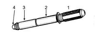
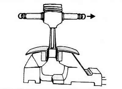
Tighten the screw loosely to avoid jamming when the piston pin expands from contact with the heated connecting rod. Remove the heated connecting rod from the oven and clamp it in a vice as quickly as possible. Put the piston on it and use the device to push the piston pin into the piston hole and into the upper head of the connecting rod so that the shoulder of the device touches the piston. In this case, the piston should be pressed with its boss against the upper head of the connecting rod in the pressing direction shown by the arrow.
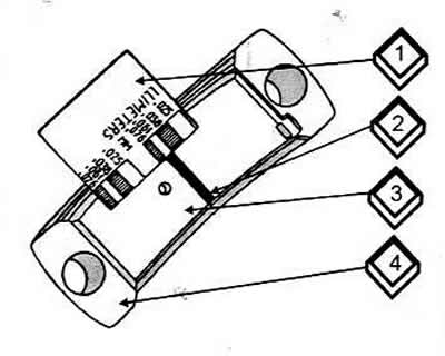
Device for testing the strength of the piston pin pressing using a torque wrench
To do this, it is necessary to clamp the base of the device in a vice and lower the indicator bracket (8).
Install the assembled piston with the connecting rod on the device and insert the threaded rod (3) into the pin hole until its head (2) rests against the end of the pin. Screw the nut (5) onto the opposite end of the rod so that it contacts the support and possible gaps are selected. Install the stop (6) in the groove of the rod, preventing it from turning. Raise the bracket (8) to a horizontal position, secure it with the handle (7) and install the indicator (9), the pin (1) of which rests against the head (2) of the rod. Set the indicator to zero.
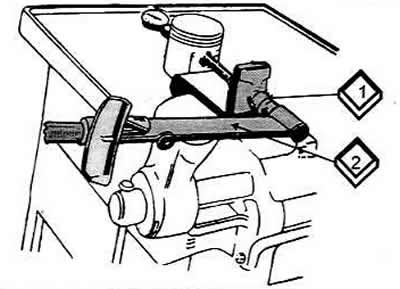
Using a torque wrench (2), apply a torque of 13 Nm to the nut (1), which corresponds to an axial load of 2 kN. Lower the dynamometer. The indicator arrow should return to zero. If the pin has moved in the connecting rod head, the connecting rod must be replaced.
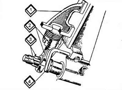
Device for checking the parallelism of the axes of the piston pin and the lower head of the connecting rod
Lower connecting rod head (without inserts) must be installed on the device and centered with retractable knives (2). Install the gauge (4) on the piston bottom and use a set of feeler gauges to determine the gap between the vertical plate of the device and the vertical plane of the gauge at a distance of 125 mm from the corner or upper end of the gauge. The location of the measurement depends on what the gauge touches the vertical plate with - the corner or the upper end. A gap of no more than 0.4 mm is allowed. If the gap is larger, the connecting rod must be replaced.
Grinding machine and fixture for grinding main and connecting rod journals of the crankshaft
Using a flange (1) and a split bushing (2), the crankshaft is mounted on a grinding machine. Depending on the wear of the crankshaft journals, they are ground to the required dimensions.
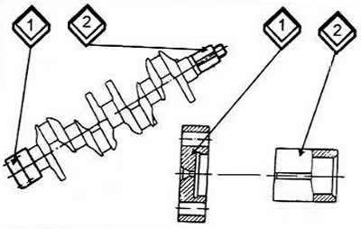
1 Flange
2 Split bushing.
Prisms for checking the geometric parameters of the crankshaft
To do this, it is necessary to install the crankshaft on two prisms and use an indicator to check the runout and misalignment of its journals.
Cutter and cutter mandrel for machining crankshaft plug sockets
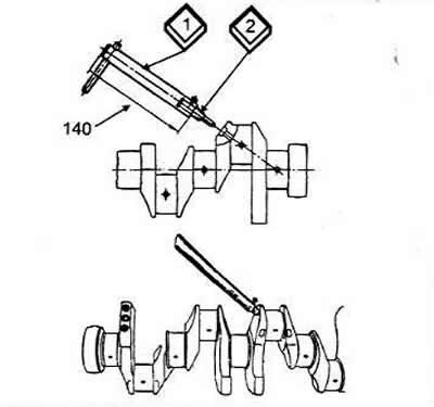
After grinding and subsequent finishing of the engine crankshaft journals, it is necessary to remove the oil channel plugs and process the plug seats with a cutter (2) mounted on a mandrel (1). Thoroughly wash the crankshaft and its channels with gasoline and blow them out with compressed air.
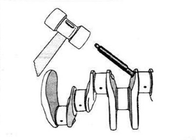
Mandrel for pressing in new plugs
After pressing in the plug, it should be punched at several points.
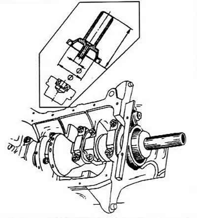
Device for measuring the axial clearance of the crankshaft on an engine installed on a vehicle
The axial movement of the crankshaft is created by pressing and releasing the clutch pedal. The value of the axial clearance is determined by the movement of the front end of the crankshaft. The maximum permissible clearance should not exceed 0.35 mm.
Mandrel for installing the rear oil seal holder (with gland) on the crankshaft
To do this, you need to lubricate the seal with engine oil and, without allowing it to sag, press it into the holder.
Mounting board — to perform repair work on the cylinder head removed from the engine.