
Table of contents: 4 and 5 cylinder engines ↓ 6-cylinder engine ↓
Attention. Before removing or installing the cylinder head, align the timing marks with the piston of cylinder No.1 in the top dead center (TDC) position.
Turn the crankshaft so that the timing mark moves away from the TDC mark by one quarter of a turn. This will prevent the valves from falling onto the piston. After installing the cylinder head, set the crankshaft to the desired position.
Note: The cylinder head should be removed after each engine cooldown.
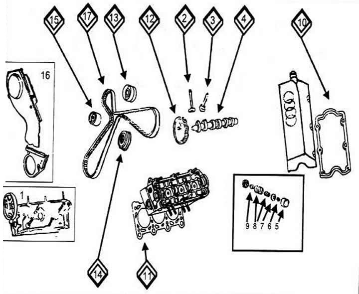
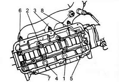
Elements of the cylinder head of a 6-cylinder engine
1 Cylinder head
2 Exhaust valve
3 Inlet valve
4 Camshaft
5 Hydraulic pusher
6 Rusks
7 Top plate
8 Spring
9 Oil deflector cap
1Top cover gasket
11 Cylinder head gasket
12 Camshaft gear
13 Tension roller
14 Toothed belt
15 Idler pulley
16 Timing belt cover
17 Idler pulley
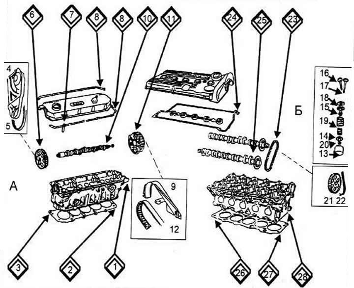
Elements of the cylinder head of a 5-cylinder engine
A Two-valve per cylinder engine
B Engine with 4 valves per cylinder
1 Cylinder head
2 Cylinder head gasket
3 Set of gaskets (during engine repair)
4 Timing belt cover
5 Toothed belt
6 Camshaft gear (front)
7 Valve guide bushing
8 Top cover gasket
9 Timing belt cover (rear)
1Camshaft
11 Camshaft gear (rear)
12 Toothed belt (rear)
13 Hydraulic pusher
14 Upper spring plate
15 Oil deflector cap
16 Exhaust valve
17 Inlet valve
18 Lower plate and spring retainer
19 Valve springs
2Valve crackers
21 Toothed belt
22 Camshaft gear
23 Chain
24 Gasket
25 Camshafts
26 Gasket
27 Set of gaskets (during engine repair)
28 Cylinder head
4 and 5 cylinder engines
Disconnect the wire from the negative terminal of the battery.
Drain the coolant.
Disconnect the air duct from the throttle body on all vehicles except Quattro models. On Quattro models, disconnect the hose that runs from the air duct to the turbocharger. Disconnect the throttle cable from the throttle body.
Remove the air duct from the injector cooling fan on Quattro models.
Clean and remove the fuel injectors and all other fuel lines.
Caution: Install caps on fuel injectors and cold start injectors.
Tag and disconnect all vacuum and PCV hoses.
Remove the hose that goes from the intake manifold to the turbocharger.
Mark and disconnect all electrical wires going to the cylinder head.
Remove the intake manifold.
Disconnect all radiator and heater hoses that are attached to the cylinder head. Secure them to the side.
Mark and disconnect all high voltage wires from the spark plugs.
Remove the distributor. To facilitate installation, scratch a mark on the distributor housing and cylinder head.
Separate the exhaust manifold from the exhaust pipe.
Disconnect the exhaust gas recirculation (EGR) valve and oxygen sensor from the exhaust manifold.
Detach the heat reflector shield.
Disconnect all oil lines (2 pieces) from the turbocharger.
Remove the exhaust manifold.
Caution: When removing the exhaust manifold on Quattro models, the manifold, turbocharger and exhaust chamber must be removed as a single unit.
Remove the air hose cover from the rear of the generator.
Tag and disconnect all wires coming out of the back of the alternator and remove the alternator from the engine.
Tag and disconnect the hoses coming from the power steering pump.
Remove the power steering pump and V-belt.
Remove the timing belt cover and the belt itself.
Remove the valve cover.
Loosen the cylinder head bolts in the reverse order used for tightening.
Unscrew the bolts and remove the cylinder head.
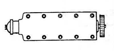
Cylinder Head Bolt Tightening Sequence - 4 Cylinder Engines
5-cylinder engines
Installation
Thoroughly clean the mating surfaces of the block and cylinder head and install a new gasket without sealant. Make sure the words "TOP" and "OBEN" are facing up. Install the head on the block and install bolts #8 and #10 first. Their holes are smaller and they will correctly center the gasket and head on the cylinder block.
Install the remaining bolts. Tighten them sequentially in three stages as follows:
- Stage No.1: torque 39 Nm.
- Stage No.2: torque 58 Nm.
- Stage #3: turn half a turn (180°).
Install the valve cover.
Install the timing belt and timing belt cover.
Install the power steering pump and drive belt.
Install the generator and all wires.
Install the exhaust manifold.
Connect the two oil lines to the turbocharger.
Install a heat reflective shield.
Connect the EGR valve and oxygen sensor to the exhaust manifold.
Connect the exhaust system.
Install the distributor and spark plug wires.
Install the intake manifold.
Install the radiator and heater hoses.
Install fuel injectors. Connect air line.
Connect the throttle cable
Connect the wire to the negative terminal of the battery.
Fill the cooling system and bleed air. Check all fluid levels.
Test drive the car
6-cylinder engine
The procedure below is for the left cylinder head, when the engine is installed in a vehicle. For the right cylinder head, this procedure must be modified accordingly.
Disconnect the wire from the negative battery terminal. Drain the coolant. Relieve the fuel pressure.
Remove the V-belt.
Remove the timing belt. The vibration damper must remain installed.
Remove the exhaust pipe from the manifold.
Remove the air duct hose between the air flow sensor and the intake manifold.
Remove and mark all spark plug wires and injector plugs.
Remove the crankcase ventilation tubes on the right and left cylinder head covers.
Remove the fuel supply and return pipes. Remove the muffler.
Remove the left fuel line cover.
Disconnect the throttle cable.
Tag and remove all vacuum hoses from the vacuum pump and intake manifold.
Disconnect the plug on the idle speed control valve and the throttle valve potentiometer.
Disconnect the vacuum hose from the vacuum control unit.
Disconnect the plugs from the oil pressure sensor and the oil pressure warning light switch.
Disconnect the plug from the Hall sensor.
Remove the EGR hose from the intake manifold.
Remove the intake manifold assembly.
Remove the coolant pipe from the rear of the cylinder head.
Remove the oxygen sensor.
Remove the heat shield on the exhaust manifold.
Remove the cylinder head cover.
Remove the timing belt and rear belt guard. Remove the hydraulic hose that runs from the reservoir to the pump.
Loosen the bolts in the reverse order of tightening and remove the cylinder head from the engine.
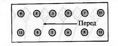
Tightening sequence of cylinder head bolts for 6-cylinder engine
Installation
Clean all mating surfaces. Check the cylinder head for deformation. Take measurements at several points. The maximum permissible deformation value is 0.1 mm.
Install the cylinder head gasket. The letters on the gasket should be facing up.
Install the cylinder head using the centering pins on the cylinder block.
Insert the cylinder head bolts by hand.
Tighten the head bolts in the sequence shown in the figure in two stages:
- Stage No.1: 6Nm.
- Stage #2: turn half a turn (180°).
Install the rear toothed roller guard.
Install the cylinder head cover.
Install the oxygen sensor. Install the heat shield on the exhaust manifold.
Install the intake manifold.
Install the EGR valve on the intake manifold.
Connect the plugs to the Hall sensor, to the oil pressure sensor and the oil pressure warning lamp switch.
Connect the plugs to the idle speed control valve and the throttle valve potentiometer.
Install all vacuum hoses to the vacuum pump and intake manifold.
Connect the throttle cable.
Connect the fuel supply and return pipes. Install the muffler.
Install the crankcase ventilation tubes to the cylinder head cover.
Install all spark plug wires and connect injector plugs.
Install the exhaust manifold.
Install the timing belt and V-belt.
Fill the cooling system and bleed air.
Check all fluid levels. Run the engine at normal operating temperature and check for leaks.
Test drive the car.