
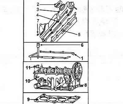
1 Lid gasket
2 Oil change hole
3 Cylinder head cover
4 Reinforcement bar
5 Oil deflector plate
6 Cylinder head bolt
7 Nut, 10 Nm
8 Generator bracket
9 Cylinder head gasket
1Cylinder head
11 Sealing insert, replaceable every time
Disassembling the cylinder head
Before performing work, unscrew all cylinder head attachments.
Clamp the head in a vice using the clamp screwed onto the exhaust manifold studs.
Gradually and alternately loosen the camshaft bearing caps #1 and #3 on each side and remove them. Cap #4 is missing on this engine.
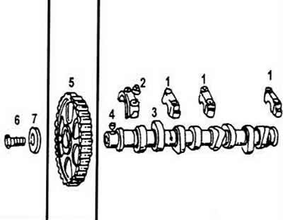
1 Camshaft bearing caps
2 Bearing cap nut, 20 Nm
3 Camshaft
4 Key
5 Camshaft drive gear
6 Bolt, 80 Nm
7 Washer
Loosen the nuts of bearing caps #2 and #5 gradually by two turns, crosswise, until both caps are released. Remove the oil backflow protection in place of the fourth cap. Mark the sealing ring in cap #1. It is best to do this by making marks on the inside, i.e. for the first tappet - one line, for the second - two lines, etc. You should start from the side of the timing drive. The tappets should not be laid on their sides, but installed with the contact surface down. Mark the hydraulic tappets on the inside with marks in the order of installation.
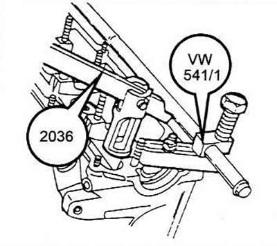
To remove the valves, you will need a valve puller. The pressing device presses on the upper spring plate to compress the spring. The device is put on the cylinder head. The lever of the device must be pressed down. The piston of the device must enter the recess on the inside of the spring, since otherwise the spring cannot be compressed. Compress the spring so that you can pull out the crackers.
To remove the valve, you can use a piece of pipe, placing it on the upper spring plate. On the other side, place something under the valve plate. Hit the pipe with a hammer to remove the crackers. They will fall inside the pipe. The pipe should be pressed well against the valve plate so as not to lose the crackers.
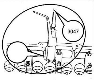
Remove the spring retainers and springs. Remove the valve stem seals and discard them as they will need to be replaced with new ones. Remove the lower spring retainer from the bore using tool 3047 or an internal crimping ring puller.
Before assembling the cylinder head, please read the following instructions carefully:
The camshaft bearing caps must be installed in a specific order. The order in which the cap bolts are installed and tightened is very important.
It is necessary to measure the bearing clearances and the axial clearance of the camshaft. When replacing the camshaft, it is necessary to install a shaft that corresponds to the engine type.
The woodruff key must fit securely into the shaft.
The semicircular sealing insert should be replaced every time.
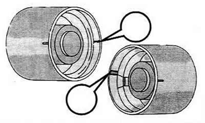
Before installing hydraulic tappets, check them every time.
Observe the correct installation direction of the valve spring plates when assembling the valves.
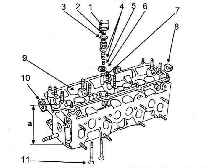
Cylinder head parts
1 Hydraulic pusher
2 Crackers
3 Valve spring plate
4 Valve spring
5 Valve stem seal
6 Valve spring seat
7 Valve guide bushing
8 Sealing insert
9 Cylinder head, a - cylinder head height
10 Camshaft oil seal
11 Valves