



Remove bearing caps No.5, 1 and 3 of the camshaft, then alternately crosswise unscrew the nuts of the studs securing bearing caps No.2 and 4.
Remove the camshaft from the cylinder head supports and remove the valve lifters.
Install a valve spring compressor or a special VW 541 device for removing and installing valve crackers on the cylinder head; using pliers with pointed ends, release the valves from the crackers by first pressing the lever of the special device.
Remove the valve springs with plates.
Remove the valve stem oil seals and spring support washers using pliers.
Remove the valves.
Clean parts with gasoline or trichloroethylene.
Check the degree of wear of the valve guide bushings and the clearance between the bushings and the valve stems.
Insert the new valve into the guide bushing so that the highlander of the valve stem is level with the edge of the guide bushing, and determine the clearance between the valve stem and the guide bushing using the VW 387 device with an indicator, resting its leg on the valve head.
Replace the guide bushings if the clearance exceeds the maximum permissible limit, which is 1.0 mm for intake valves and 1.3 mm for exhaust valves.
Check whether the flatness of the mating surface of the cylinder head is damaged using a straightedge and a set of feeler gauges. It is best to perform this check on a test plate.
If necessary, grind the mating surface of the cylinder head within the permissible limits (see subsection "Design and technical characteristics").
Check the condition of the valve and valve springs.
Check the condition of the valve seats and grind them if necessary. Grinding is performed with a special tool in compliance with the permissible limits (see subsection "Design and technical characteristics").
If necessary, grind the working chamfers of the inlet valves. The working chamfers of the outlet valves are not subject to grinding; grinding of the outlet valves is allowed; in other cases, they are subject to replacement.
Before assembly, as well as after grinding the valve seats and lapping the valves, thoroughly clean the cylinder head.
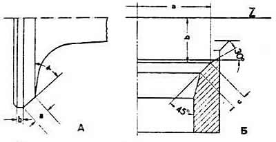
Basic dimensions for grinding valves and valve seats:
A - inlet valve:
α — working chamfer angle (45°);
a — width of the working chamfer;
b — height of the valve head edge.
B - valve seat (inlet and outlet):
Z — cylinder head plane;
a — outer diameter of the working chamfer;
b — distance from the working chamfer of the valve seat to the plane of the cylinder head;
c — width of the working chamfer of the valve seat.
(Information obtained from this resource: «AUDIMANUAL»)