
Repair Chevrolet Repair Toyota Repair Honda Repair AvtoVAZ Repair Mercedes-Benz Repair BMW Repair Opel
Home  |  Contacts  |  Sitemap  |    
English Русский
Български
Беларускі
Український
Српски
Hrvatski
Română
Polski
Slovenský
Magyar
AudiManual.ru


  • AUDI 80
  • AUDI 100
  • AUDI A3
  • AUDI A4
  • AUDI A6
  • AUDI A8
  • AUDI Q
  • OTHER
  • ARTICLES
B4 (1991-1996) B3 (1986-1991) B3 (1986-1991, petrol) B2 (1979-1986)

Removal and installation of carburetor engines (Audi 80 B2)

  • Home
  • Audi 80
  • B2 (1979-1986)
  • Power unit
  • Engine EP, YP, YZ, DT, DS, DZ
  • Removal and installation of carburetor engines
            0
Table of contents: Installation ↓ Removal and installation of engines… ↓
Removal

Place the engine on a lift and remove the hood.

Disconnect the wire from the negative terminal of the battery.

Set the heater control handle to the "warm" position.

Remove the air filter and close the carburetor with a technological plug.

Remove the cap from the radiator.

Drain the coolant from the cooling system by disconnecting the drain hose from the radiator.

Loosen the tension on the clutch cable and disconnect it from the clutch release fork.

Disconnect the cooling system supply hose from the engine, coming from the radiator.

Disconnect the hose leading to the expansion tank from the radiator pipe and drain the liquid.

Disconnect the drain hose from the water pump.

Disconnect the heater coolant drain hose from the rear of the cylinder head and the radiator drain hose.

Loosen the bolt race securing the silent block to the right engine mount bracket.

Remove the front engine mount bracket.

Disconnect the electric fan switch connector on the radiator.

Disconnect the hose from the upper radiator inlet pipe.

Disconnect the upper silent block of the engine mount from the body.

Disconnect the cooling system electric fan connector.

Remove the radiator.

Unscrew the bracket for mounting the muffler inlet pipe from the exhaust manifold flange.

Disconnect the exhaust pipe from the rubber holders.

Remove the protective shield.

Loosen the nut of the bolt securing the left silent block to the subframe.

Disconnect the wires from the starter.


Place a hydraulic jack or other support under the gearbox (for example, VW 785/1).

Remove the upper transmission-to-engine mounting bolts and release the lower coolant drain hose.

Disconnect the left engine mount bracket from the subframe.

Place the gearbox on a support or hydraulic jack.

Note: Secure the hoist ropes and hooks taking into account the center of gravity.


Raise the engine using a hoist to free the engine mounting brackets.

Separate the engine from the gearbox.

Raise the engine at a slight angle and remove it from the powertrain compartment.

Installation


The engine is installed in the reverse order of removal. Finally tighten the engine mounting bolts to the suspension brackets with the engine idling. Pay attention to the correct connection of the wires to the starter.

Removal and installation of engines with fuel injection system


Removal and installation of fuel injection engines are carried out in the same way as carburetor engines, taking into account the following:
  • disconnect the connectors of the control pressure regulator from the thermal time relay, the additional air supply valve and the starting nozzle;
  • remove a bundle of electrical wires;
  • remove the control regulator from them and disconnect the fuel lines from it;
  • unscrew the injection nozzles from their sockets without disconnecting the fuel lines;
  • remove the cold start injector without disconnecting the fuel line;
  • close the injection and starting nozzles with plugs.

Install the engine in the reverse order of removal.
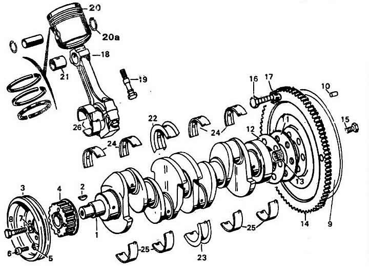
Crank mechanism parts: 1 - crankshaft; 2 - segment key; 3 - crankshaft pulley; 4 - toothed pulley…

Crank mechanism parts: 1 - crankshaft; 2 - segment key; 3 - crankshaft pulley; 4 - toothed pulley of the crankshaft; 5 - stopper; 6 - crankshaft toothed pulley mounting bolt; 7 - washer; 8 - crankshaft pulley mounting bolt; 9 - flywheel; 10 - mounting pin; 11, 12 - washers; 13 - gearbox primary shaft needle bearing; 14 - toothed flywheel gear; 15 - flywheel mounting bolt; 16 - ring gear mounting bolt; 17 - retaining ring; 18 - connecting rod; 19 - connecting rod bolt; 20 - piston; 20a - piston pin retaining ring; 21 - connecting rod upper head bushing; 22, 23 - set of liners with thrust flanges of the middle main bearing; 24, 25 - crankshaft main bearing shells; 26 - connecting rod bearing shells.
The article was checked by auto expert Georgy Rodionov
This article is available at russian, bulgarian, belarusian, ukrainian, serbian, croatian, romanian, polish, slovak, hungarian

Share information:
Previous articles
Audi 80 B2: Engine EP, YP, YZ, DT, DS, DZ
Next articles

Cylinder head assembly
Disassembly and repair of the cylinder head
Installing the cylinder head
Removal the cylinder head
Disassembling the engine
Engine assembly
Checking the clearances between the bearings and the crankshaft…
Engine assembly


Similar articles on other Audi car models:
Electrical equipment diagram of AUDI «100» cars with carburetor… Audi 100 C3 (1982-1990, petrol)
Engines — General Information Audi A4 B5 (1994-2001, petrol)
Fuel filter for TDI diesel engines Audi A6 C5 (1997-2004)
General information about 3.7 and 4.2 liter petrol engines Audi A8 D2 (1994-2002)
Removal the starter, cars with 2.0 l T01 engines and manual… Audi Q5 Type 8R (2008-2017)
Brief description of engines Audi A2 (1999-2005)
Link to this page in different formats


Visitor comments

No comments yet


How much will 36 + 43 =


80(B4, 1991-1996) 
  • General information
  • User manual
  • Maintenance
  • Troubleshooting
  • Power unit
  • Engine
  • Cooling system
  • Heating and ventilation
  • Petrol injection
  • Diesel fuel system
  • Fuel system
  • Exhaust systems
  • Ignition system
  • Transmission
  • Clutch
  • Car gearbox
  • Chassis
  • Brake system
  • Suspension and steering wheel
  • Body
  • Body and trim
  • Electrical equipment
  • Electrical system
  • Electrical circuits
 
80(B3, 1986-1991) 
  • General information
  • Repair characteristics
  • Maintenance
  • Power unit
  • Gasoline engine
  • Diesel engine
  • Engine lubrication system
  • Fuel system (gasoline)
  • Injection system (gasoline)
  • Fuel system (diesel)
  • Ignition system
  • Cooling system
  • Heater
  • Exhaust system
  • Transmission
  • Clutch and gearbox
  • Chassis
  • Steering
  • Brake system
  • Car suspension
  • Body
  • Body elements
  • Electrical equipment
  • Power devices
  • Lighting and appliances
  • Electrical circuits
 
80(B3, 1986-1991, petrol) 
  • General information
  • User manual
  • Maintenance
  • Power unit
  • Engine 4-cylinder
  • Engine 5-cylinder
  • Cooling system
  • Fuel and exhaust systems
  • Ignition system
  • Transmission
  • Clutch
  • Mechanical transmission
  • Automatic transmission
  • Drive shafts
  • Chassis
  • Brake system
  • Suspension
  • Steering
  • Body
  • Exterior
  • Interior
  • Electrical equipment
  • Equipment and devices
  • Electrical circuits
 
80(B2, 1979-1986) 
  • General information
  • User manual
  • Power unit
  • Engine FZ
  • Engine EP, YP, YZ, DT, DS, DZ
  • Transmission
  • Clutch
  • 4 speed gearbox
  • 5 speed gearbox
  • Front wheel drive
  • Chassis
  • Front suspension
  • Rear suspension
  • Steering
  • Brake system
  • Electrical equipment
  • Equipment and devices
  • Electrical circuits
 
AudiManual.ru © 2017-2026 · Mobile version · Feedback · Sitemap: EN BG BY UA RS HR RO PL SK HU · Site search · News and articles
80 B2 · 80 B3 petrol · 80 B3 · 80 B4 · 100 C3 diesel · 100 C3 petrol · 100 C3 · 100 C4 petrol · 100 C4 · A3 Type 8L · A4 B5 petrol · A4 B5 · A4 B6 petrol · A4 B6 · A4 B7 · A4 B8 · A6 C4 · A6 C5 · A6 C5 Allroad · A8 D2 · Q5 Type 8R · Q7 Typ 4L · Audi A2 ·
This site uses cookies 🍪. Click the button to accept this fact.