



Note: When disassembling, apply marks to the removed parts that are suitable for further use, so that when reassembling, they can be installed in their original places and in their original position.
Place the washed and cleaned engine on a stand for disassembly.
On carburetor engines, the carburetor shines.
Remove the intake manifold and exhaust manifold.
Remove the distributor flange, ignition distributor and generator.
Remove the water pump.
On carburetor engines, remove the fuel pump.
Remove the oil pan, then the crankshaft pulley and the camshaft drive belt protective covers.
Loosen the timing belt tension roller axle mounting nut and remove the belt.
Remove the cylinder head.
Loosen the bolts securing the clutch housing to the flywheel and remove the housing together with the pressure plate. This will release the driven clutch disk.
Remove the flywheel.
Loosen the mounting bolts and remove the front and rear crankshaft oil seal holders together with the latter using two screwdrivers, resting them on the lugs.
Remove the intermediate shaft from the cylinder block, having first removed the holder together with the oil seal.
Place the cylinder block on a support.
Apply marks to the connecting rods, crankshaft main bearing caps and the corresponding cylinders. Make sure that the connecting rod caps and crankshaft main bearing caps are marked.
Loosen the connecting rod bolt nuts and remove the connecting rod caps.
Remove the pistons with connecting rods through the cylinders.
Remove the connecting rod bearing shells and determine the degree of wear of the shells. If the shells can be used again, mark the shells to determine their position ("top", "bottom") and mark the corresponding connecting rods.
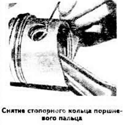
Loosen and remove the piston pin retaining rings using round-nose pliers and press out the pins using a mandrel.
Check the axial free play of the crankshaft.
Loosen the main bearing cap mounting bolts and remove the caps together with the lower bearing shells.
Remove the crankshaft from the bearing seats, and then the upper bearing shells.
The main bearing caps are marked with numbers 1-5, indicating the order in which they were installed during engine assembly. If the main bearing shells are to be reused, both the lower and upper shells must be marked.
(The text is based on materials from the website «AudiManual.ru»)