



Select the main bearing caps with liners and install them on the block bed. Tighten the cap mounting bolts to a torque of 6.5 kgf·m.
Note: When installing, the projections on the main bearing caps must align with the protrusions on the lower bearing shells.
Measure the free axial movement of the crankshaft on the third support with a set of feeler gauges, which should be within 0.07-0.17 mm. If the gap exceeds the maximum permissible 0.25 mm, and the crankshaft main journals are not ground, install bearings with flanges of the nominal size on the third support. If the main journals are ground to the repair size, install bearings with flanges of the corresponding size on the third support.
Install three piston rings into the corresponding grooves in the pistons, arranging their locks at 120° intervals.
Orient the piston ring locks forward or backward in the direction of the vehicle. The lower compression and oil release rings are marked "top" or "oben" ("top"), which should be turned up when installing the ring in the groove.
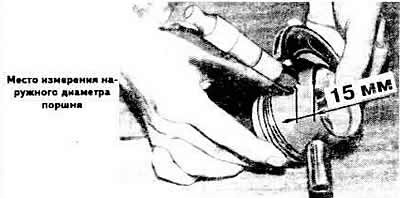
Check the diameter markings on the piston crowns.
Install the pistons by orienting the arrow on the piston bottom forward in the direction of vehicle travel (towards the camshaft drive).
Assemble the pistons with connecting rods. The connecting rods of one engine must belong to the same weight group, which is marked on the connecting rod caps.
Lubricate the pistons and piston rings with engine oil, compress the piston rings in the grooves with the appropriate mounting sleeve and insert the pistons with connecting rods into the cylinders.
Install the bearing shells into the connecting rods and connecting rod caps in accordance with the marks made during disassembly if worn bearing shells are used.
Install the connecting rods and caps on the crankshaft journals, with the projections on the caps and the locking protrusions on the liners facing the intermediate shaft.
Screw on the connecting rod bolt nuts, then tighten them to a torque of 3.5 kgf·m.
Note: Replace connecting rod bolts each time the engine is reassembled.
Note: When assembling the engine, always install new crankshaft seals. The use of used seals is not permitted.
Install the rear oil seal holder with a new cardboard gasket. Press the oil seal into the holder with mandrel 2003/1 until it stops.
Install the flywheel, ensuring that the surface under the driven clutch disc protrudes relative to the cylinder block within 30.50-32.10 mm.
If necessary, install a spacer washer between the flywheel and the crankshaft flange. Install a lock washer on the flywheel with the beveled edge facing the flywheel. Apply special glue to the mounting bolts beforehand.
Install the front crankshaft oil seal holder with a new cardboard gasket. Press the new oil seal into the holder using mandrel 3083.
Insert the intermediate shaft into the cylinder block. Install the holder with the pressed-in oil seal and sealing gasket onto the intermediate shaft.
Install the oil pump, having first checked its technical condition.
Install the oil pan with a new gasket.
Install the cylinder head.
Install the camshaft drive belt.
Install the water pump.
The original version is on the portal: AudiManual