
Table of contents: Disassembling the cylinder head ↓ Cylinder head assembly ↓ Installing the cylinder head ↓
Disassembling the cylinder head
The camshafts can be removed and installed on an installed engine by performing some preliminary operations.
To pre-tension the chain tensioner, a special device is used, which will be discussed below.
Remove the front of the car.
Remove all drive belts located in front of the engine, i.e. the ribbed V-belt and the V-belt.
Remove the upper timing belt cover.
Mark the direction of rotation of the toothed belt on the outside with a felt-tip pen if the belt is to be reused.
Turn the crankshaft so that the engine is in the TDC position and remove the toothed belt.
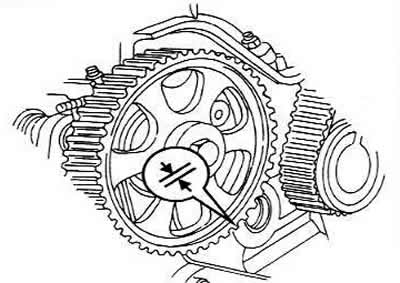
Hold the camshaft gear with a suitable means and unscrew the drive gear bolt. Pull off the gear, marking how it was mounted. The flange indicated by the arrows should be on the outside after installing the gear.
Remove the Hall sensor and light shield (blend).
Unscrew the cylinder head cover.
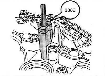
Place the chain tensioner locking tool (#3366) on the cylinder head and tighten until you feel a stop. If you tighten the tool too tightly, you can damage the chain tensioner. The tool prevents the chain from falling off.
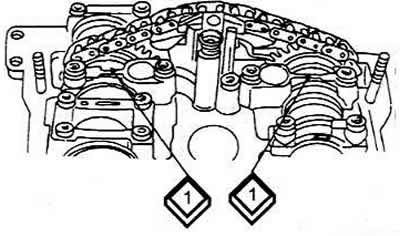
Turn the drive chain and both sprockets so that they are opposite the two arrows (1) on the bearing cover #6. Clean the chain and sprockets and mark their relative positions with paint. Wait until the paint dries. You need to count the number of teeth between the two arrows. There should be 16 teeth in total, which will be important during assembly.
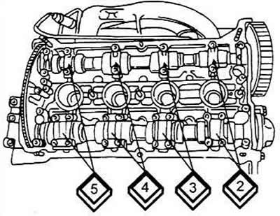
Now you need to release the camshaft bearing caps in the order shown. The caps are numbered at the top to avoid confusion. First, unscrew the cap bolts #1, 2, 4 and 6 (both shafts), and then unscrew the belt tensioner.
Loosen the bearing cap bolts #3 and #5 of both camshafts crosswise in several passes until they are completely free of tension, remove the bolts and caps.
Pull out the camshafts. At the same time, you need to disengage the chain and both sprockets. Again, it is worth remembering that you need to mark the position of the sprockets and chain if these parts are to be reinstalled. If the chain is not installed correctly, it will wear out very quickly and will have to be replaced.
Pull out the tappets. They cannot be mixed up, so they should be marked. It is best to put the marks on the inside, i.e. one mark on the first tappet, two on the second, etc. You should start from the side of the timing drive and be sure to mark whether the tappet belongs to the inlet or outlet part. Do not lay the tappets on their sides, but place them with the contact surface facing down.
Due to the way the valves are installed, removing the exhaust valves is somewhat more difficult - since it is not so easy to get to the valve springs from this side. The recommended tool for removing and installing the valves is number 2036. Tool 2036 is a screw-on iron rod under which the lever of the VW541/1 valve puller can be placed in order to compress the valve springs using the VW541/5 piston.
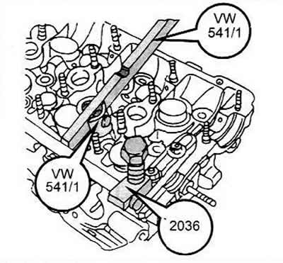
A regular valve puller is suitable for removing the exhaust valves. When using a valve puller, the piston of the tool must be positioned inside the valve spring recess, otherwise the spring cannot be compressed. Compress the spring until the cracker halves can be removed.
To remove the valves, you can use a piece of pipe that needs to be placed on the upper spring plate. You need to put something under the spring plate. Hit the pipe with a hammer so that the crackers can come out. They will be inside the pipe. The pipe should be pressed well against the valve plate so as not to lose the crackers.
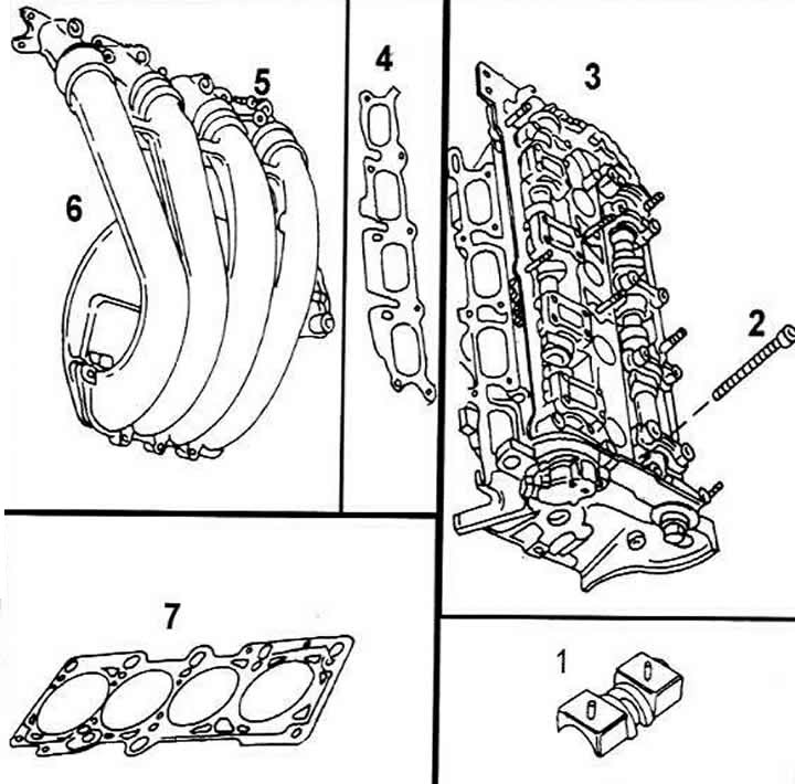
Cylinder head
1 Oil deflector plate
2 Cylinder head bolt (is replaced every time)
3 Cylinder head
4 Intake manifold gasket
5 Bolt, 10 Nm
6 Intake manifold block
7. Cylinder head gasket
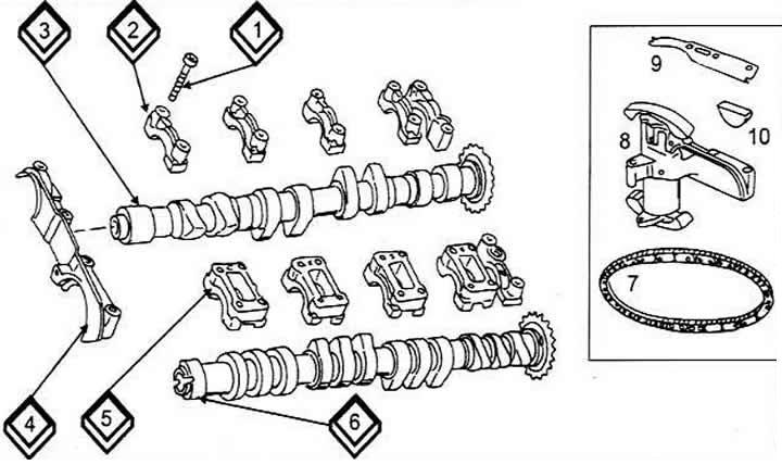
Camshafts
1 Bearing cap bolt, 10 Nm
2 The exhaust camshaft bearing cap is held in place by a guide sleeve
3 Exhaust camshaft
4 Front bearing cap
5 Intake camshaft bearing cap
6 Intake camshaft
7 Drive chain
8 Hydraulic chain tensioner
9 Rubber-metal gasket
1Semi-circular sealing insert
Remove the spring plates and springs. Pull out the valve stem seals and discard them as they need to be replaced with new ones.
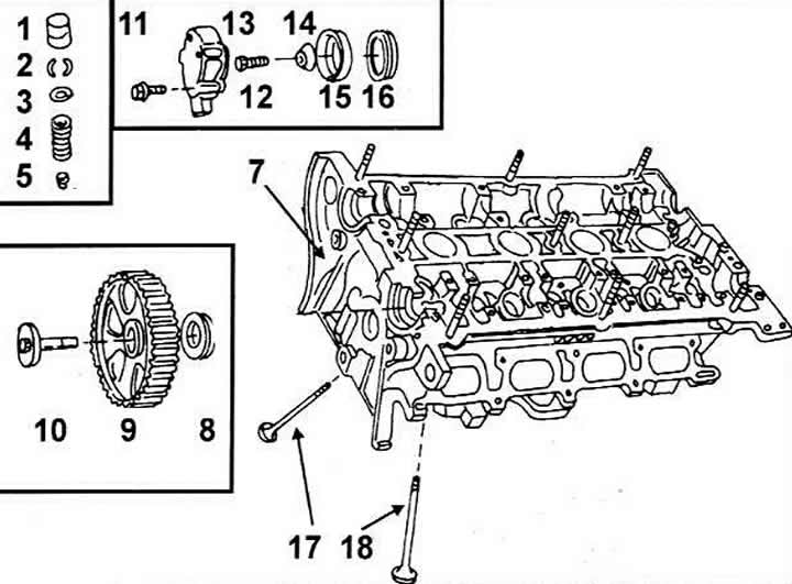
Cylinder head
1 Hollow pusher
2 Crackers
3 Valve spring plates
4 Valve springs
5 Valve stem seal
6 Guide pin
7 Cylinder head
8 Oil seal on the toothed belt side
9 Camshaft drive gear
1 Bolt, 85 Nm
11 Bolt, 10 Nm
12 Hall sensor
13 Bolt, 25 Nm
14 Figured washer
15 Hall sensor socket
16 Seal at the end of the Hall sensor
17 Exhaust valve
18 Inlet valve
Cylinder head assembly
Lubricate the valve stems well with engine oil and insert them into the corresponding guide bushings.
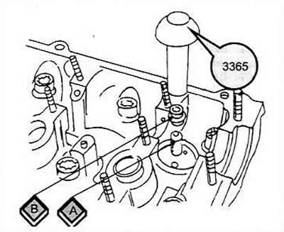
Install the valve stem seals. The appropriate tool (3365) is available for this purpose.
Slide the plastic sleeve (A) of the tool onto the protruding valve guide sleeve.
Lubricate the seal (B) well and place it on the plastic sleeve.
Place tool 3365 on the seal and carefully press it into the guide bushing. Installing seals without using this tool or a similar tool can damage the seals, resulting in increased oil consumption.
If the valves have been lapped, they must be installed in their corresponding guide bushings.
Install the valve springs in their original locations on the cylinder head if the springs are being reinstalled.
Install the upper valve plates. Place the puller, then compress the springs or not, depending on whether we are talking about intake or exhaust valves. After the end of the rod comes out of the upper valve plate, place both crackers in the groove of the rod and slowly release the valve puller.
Hit the top of the valve stem with a plastic hammer. Incorrectly installed crackers will pop out. As a precaution, place a rag under the ends of the springs to prevent installed parts from popping out.
Lubricate the bearing journals of both camshafts thoroughly with oil.
Place the hydraulic tappets in the tappet holes according to the previously made markings. They must be well lubricated with oil.
Engage both camshafts with the drive chain. Pay attention to the previously painted marking, i.e. the mark should be against the arrow. There should be 16 chain links between both arrows. When installing the camshafts, the cams for the first cylinder should be directed vertically upwards.
Lubricate the shaded surface of the rubber gasket with sealant (AMV 188 001 02). The semicircular sealing sleeve must be replaced with a new one every time.
Install the chain tensioner on the chain, lubricate the camshaft bearing journals well and install the camshafts together with the chain and chain tensioner in the inner diameters of the bearings. Immediately screw on the chain tensioner.
Install the camshaft bearing caps in order according to the numbers and screw them on loosely.
Tighten bearing caps #3 and #5 alternately, crosswise, in several passes with a tightening torque of 10 Nm. In this case, the camshaft is pressed into the inner diameters of the bearings without damaging the latter. Tighten the caps of both camshafts in the manner described.
Install bearing caps No.6 on both camshafts. Again check that the camshafts are correctly aligned and tighten both bearing caps evenly to a torque of 10 Nm.
Unscrew and remove the device used to lock the chain tensioner.
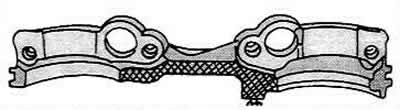
Install the double bearing cap, i.e. the front one, after having lubricated it with sealant in the shaded area on the figure above the camshaft, onto the cylinder head. Tighten the bolts to 10 Nm.
Tighten the remaining bearing caps evenly, crosswise, to a torque of 10 Nm.
Install the camshaft seals on the timing drive side and on the Hall sensor side.
Take the camshaft drive gear in your hand and place it on the camshaft, paying attention to the flange. Hold the gear in place with a suitable method (for example, by inserting a rod through a hole in a gear), tighten the bolt with the washer to 85 Nm. The cylinder head is now ready for installation if all other parts are installed.
Rotate both camshafts several times to check for binding.
Installing the cylinder head
Before installing the cylinder head, the following must be done:
Cylinder head bolts must be replaced every time.
The threaded holes in the cylinder block are blind, which means that any oil that gets into them must be removed so that a hydraulic cushion is not created when tightening the bolts.
Before installing the cylinder head, turn the crankshaft until the piston of the first cylinder is at top dead center.
Clean the cylinder head and block surfaces again.
To ensure precise installation of the cylinder head gasket, the cylinder block has centering pins. Place the cylinder head gasket on the pins so that the word "OBEN/TOP" or the part number after installation of the gasket is visible from above. A new gasket should be installed each time.
Install the cylinder head and hammer it in with a plastic or rubber hammer.
Insert the cylinder head bolts and tighten by hand.
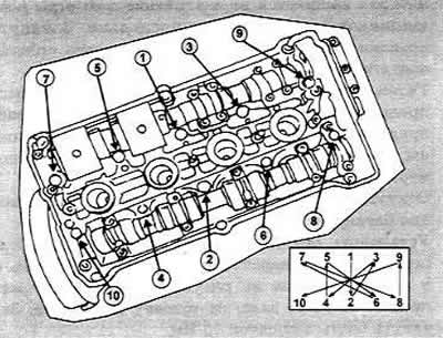
Tighten the cylinder head bolts alternately in the order shown. Use only the special multi-sided wrench to tighten the bolts, otherwise the bolt heads may be damaged. Damaged bolts must be replaced.
- Tighten all bolts in the specified order to a torque of 4 Nm.
- Tighten all bolts in the specified order to a torque of 6 Nm.
- In the order specified, insert the key into the bolt head, mark the position of the ratchet and turn each bolt exactly half a turn (or twice a quarter turn).
Note: Once tightened, the cylinder head bolts should not be tightened further, either on a cold or hot engine
Install the timing belt and adjust the timing mechanism as described in the relevant section.
Install the larger and smaller cylinder head cover gaskets and install the cylinder head cover. Tighten the bolts evenly around the circumference to 10 Nm.
Perform all other operations.