
Table of contents: Checking and tensioning the timing… ↓ Replacing the toothed belt when the… ↓
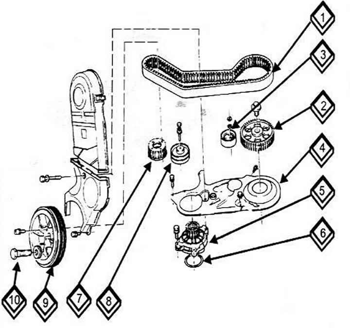
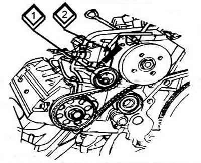
Elements of the toothed belt transmission of a 5-cylinder engine (camshaft drive)
1 Toothed belt
2 Camshaft gear
3 Tension roller
4 Rear timing belt cover
5 Coolant pump
6 Interlayer
7 Crankshaft gear
8 Idler pulley
9 Torsional vibration damper
1Crankshaft center bolt.
Checking and tensioning the timing belt
Remove the timing belt guard cover.
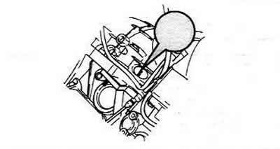
Tap the timing belt between the camshaft and the pump gear using a plastic hammer.
Loosen the spring on the VW 21 tester by turning the handle. Position the tester between the camshaft and the pump so that the toothed belt lies between the runners and the measuring tip of the tester.
Preliminarily tighten the device by the handle to the scale value of 12-13. At the same time, a steel tongue protrudes from the side of the measuring device, on which there is a white mark, which should align with the edge of the device. Otherwise, it is necessary to adjust the toothed belt.
Install the test device and then set the device scale value to 12-13.
After unscrewing the mounting bolt, turn the tension roller until the white perpendicular line on the tongue of the device is positioned opposite its body.
Tighten the roller nut to 45 Nm.
Turn the crankshaft one revolution, repeat the measurements.
Install the top cover of the timing belt housing.
Check the start of fuel supply from the high-pressure fuel pump.
Caution: If a test tool is not available, check the tension by turning the timing belt with your thumb and forefinger.
Replacing the toothed belt when the fuel injection pump is broken
Removal
After raising the vehicle, remove the inner guide cover of the engine compartment.
Lower the vehicle and remove the hood latch and front bumper
On the right side of the vehicle, remove the radiator cowling and mount.
On the left side, also unscrew the radiator mount and air duct.
Move the radiator forward and support it with a block.
After loosening the tension, remove the V-belt.
After unscrewing the bolts, remove the cylinder head cover.
Remove the protective cover of the fuel injection pump toothed belt from the rear of the cylinder head.
Remove the camshaft drive toothed belt protective cover from the front.
Indicate the direction of rotation of the toothed belt (clockwise).
Set the 1st cylinder to the TDC position. To do this, you need to:
- Set the gearbox to neutral position.
- Apply the handbrake.
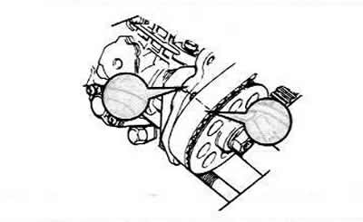
- Turn the crankshaft by the central bolt until the marks in the clutch housing window and the marks on the fuel injection pump pulley coincide.
- If the marks do not match, then it is necessary to turn the crankshaft one more revolution.
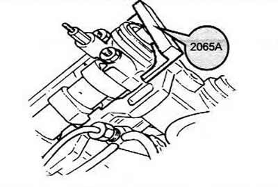
2.4L Engine: lock the fuel injection pump gear using a rod.
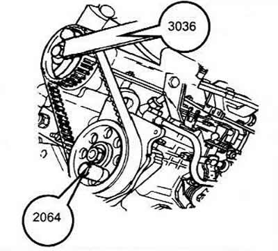
2.5L Engine: loosen the lock nut of the toothed belt tension roller and remove the spring (1).
Holding the camshaft gear with a device, loosen the mounting bolt and remove the gear and timing belt.
Using a special block, lock the camshaft so that it cannot turn.
After loosening the tension roller of the camshaft drive toothed belt, remove the toothed belt from the camshaft toothed wheel.
Using a special tool, unscrew the central bolt of the vibration damper.
After unscrewing the bolts, remove the vibration damper.
After unscrewing the bolts securing the lower casing, remove the casing and toothed belt from the gear wheel.
Installation
Check that the alignment marks match.
Secure the camshaft from turning using a block.
Loosen the camshaft timing gear mounting bolt.
Insert a punch into the hole in the rear timing belt casing until it stops against the timing gear and, by hitting the punch, loosen the seat of the camshaft timing gear.
Put on the camshaft timing belts without changing their direction of rotation.
After tensioning the toothed belt, tighten the tension roller nut to 45 Nm.
Tighten the camshaft drive wheel mounting bolt to 50 Nm.
Remove the adjusting block.
Loosen the camshaft drive wheel mounting bolt by half a turn. If necessary, i.e. also loosen the camshaft drive wheel.
Set the piston of the first cylinder to the TDC position.
Tighten the camshaft timing gear mounting bolt.
Turn the crankshaft two revolutions. Tap the toothed belt with a plastic hammer in the area: camshaft toothed wheel - fuel injection pump toothed wheel and check the toothed belt tension again. If necessary, repeat the tension again.
From the rear of the engine, put on the toothed belt and the fuel injection pump toothed wheel, then tighten the central wheel mounting bolt with a force of 50 Nm. Then unscrew the bolt again by half a turn. In this case, the toothed wheel should turn with the force of your hand.
Engine 2.4L: check the tension of the fuel injection pump drive toothed belt and, if necessary, adjust the tension by loosening the three fuel injection pump mounting bolts.
2.5L Engine: after putting on the toothed belt, install the tensioner spring.
- Loosen the tension roller mounting nut by one turn. The tension roller should be pressed against the toothed belt.
- Install the timing belt in its place by turning the engine crankshaft half a turn.
- Tighten the tension roller nut.
Install the lower timing belt guard.
After installing the device, tighten the central bolt of the vibration damper.
Further assembly is carried out in reverse order.