
Table of contents: Valve seats ↓ Valve guide bushings ↓ Valves ↓ Clearances in the valve drive… ↓ Valve springs ↓ Pushers ↓
The cylinder head without combustion chambers is cast from aluminum alloy. When casting, the heads are marked with a part number. The valve seats and guide bushings are pressed into the cylinder head. The Goetze or Elring cylinder head gasket is installed with the inscription "oben" ("top") toward the cylinder head.
Minimum permissible height of cylinder head, not less than, mm:
- engines YP, YZ: 132.55;
- engines EP, OT, OS, OZ: 132.60.
Warpage of the mating surface of the head with the cylinder block, no more than, mm: 0.1.
Diameter of bearing holes for camshaft bearings, mm: 26.00-26.02.
Diameter of pusher sockets, mm: 35.00-35.02.
Valve seats
The valve seats are made of powder metallurgy steel and are not replaceable. If traces of burning or wear are found that cannot be removed by grinding, replace the cylinder head.
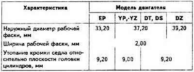
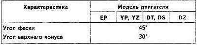
Intake valve characteristics
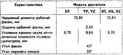
Exhaust valve seat characteristics
Valve guide bushings
Valve guide bushings are made of special brass (yP, YZ engines) or made of bronze (eP, DT, OS, DZ engines) and pressed into the cylinder head. Guide bushings supplied as spare parts have a support flange.
Pressing force of guide bushings, no more than, t.s.: 1
Maximum permissible marginal clearance (when worn out) between the valve stem and the guide bushing (the measurement procedure is described on page 67), mm:
- for intake valves: 1.0;
- for exhaust valves: 1.3.
Valve guide hole diameter, mm: 8.013-8.035.
Valves
The steel valves are located in the cylinder head in a row and are actuated directly by the camshaft cams through tappets or hydraulic tappets (dT, DS, DZ engines produced since July 1985.). Exhaust valves cannot be ground; only lapping them to the seats is permitted.
Intake valve characteristics
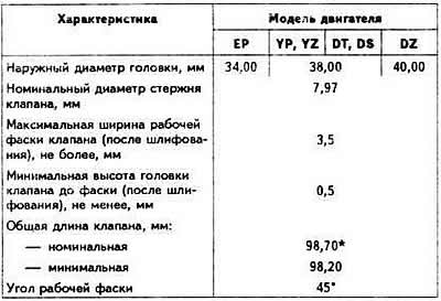
*91.00 mm since July 1985 for DT, DS, DZ engines.
Exhaust valve characteristics
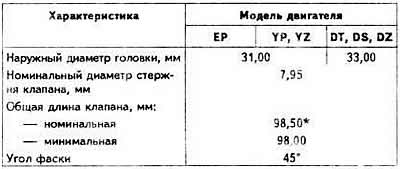
*90.80 mm since July 1985 for DT, DS, DZ engines.
Clearances in the valve drive mechanism
Engines of all models
The clearance between the camshaft cams and the adjusting washers at a coolant temperature above 35°C should be 0.25±0.05 mm for the intake valves and 0.45±0.05 for the exhaust valves; on a cold engine, 0.20±0.05 and 0.40±0.05 mm, respectively.
The clearance is adjusted by selecting the thickness of the adjusting washers installed on the upper ends of the tappets. Adjusting washers with a thickness of 3.00 to 4.25 mm with an interval of every 0.05 mm are supplied as spare parts. The thickness of the washer is marked on its lower surface. The washer is installed with the marked surface facing down.
Engines DT, DS, DZ since July 1985.
Clearances in the valve drive mechanism are compensated automatically by hydraulic tappets.
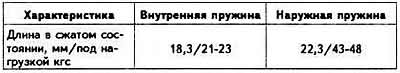
Valve springs
Each intake and exhaust valve has two springs. The intake and exhaust valve springs are the same.
Calibration characteristics of valve springs
Pushers
The valve tappets are located directly in the cylinder head. Adjusting washers of different thickness are installed on the upper ends of the tappets to adjust the thermal clearances of the valves. Since July 1985, DT, DS and DZ engines have been equipped with hydraulic tappets that compensate for the thermal clearances of the valves.