
Table of contents: Dismantling ↓ Dismantling ↓ Checking the dismantled cylinder head ↓ Installation ↓
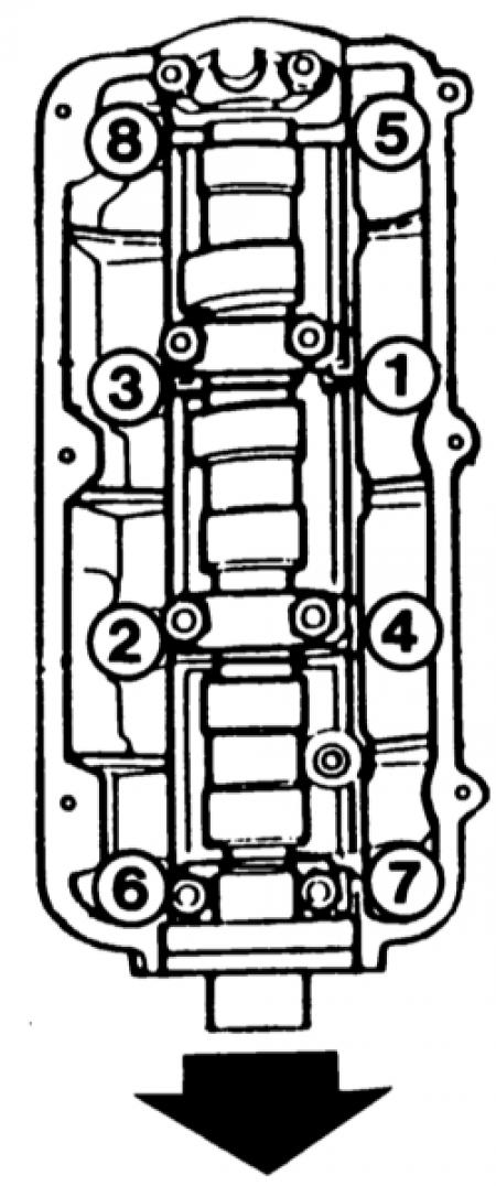
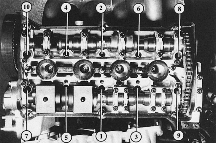
The cylinder head bolts should be tightened in the sequence indicated by the numbers. The six-cylinder engine is shown first (the arrow shows the direction of movement) and the second is a 4-cylinder engine.
You will need: a torque wrench, a long T55 internal toothed rim wrench (for four-cylinder engine) or TORX key E14 (for six-cylinder engine) and a new gasket.
Dismantling
Four-cylinder engine
1. Bring the front of the vehicle to the service position (chapter Body parts).
2. Remove the viscous fan.
3. Remove the V-belt and V-ribbed belt, unscrew the belt tensioner.
4. Drain the coolant through the radiator drain plug.
5. Remove the connector on the fresh air flow sensor, the carbon filter solenoid valve and the ignition system power output stage (only 1.8L engine).
6. Unscrew the air filter housing assembly, remove the air hose to the throttle valve branch pipe.
7. Remove the engine trim and unscrew the cylinder head cover
8. Unscrew the coolant pipe with the temperature sensor behind the cylinder head.
9. Unscrew the expansion tank with coolant.
10. Disconnect the connectors on all injection valves and on the Hall sensor.
11. For 1.6L engines, remove all spark plug connectors and the high tension wire.
12. Unscrew the intake manifold brackets.
13. Unscrew the intake manifold from the cylinder head and set it aside.
14. Disconnect the wire connector to the lambda probe, expose the wire.
15. Unscrew the exhaust pipe from the front of the elbow and push it back.
16. Remove the timing belt cover and set the piston of cylinder No.1 to the TDC position of the ignition timing, see the chapter above.
17. Loosen the tension roller mounting bolt.
18. Mark the direction of movement of the timing belt for subsequent assembly and remove it.
19. Loosen the cylinder head bolts in the reverse order of the tightening pattern from right to bottom.
Dismantling
Six-cylinder engine
1. Unscrew the engine cover and the V-ribbed belt cover.
2. Remove the V-ribbed and toothed belts (see section Generator).
3. Unscrew the exhaust pipe from the elbow.
4. Drain the coolant through the engine and radiator drain plug.
5. Unscrew the air hose between the fresh air flow sensor and the intake manifold.
6. Disconnect the connector from the Hall sensor.
7. Disconnect the crankcase ventilation on the cylinder head on the left and right.
8. Remove the vacuum hose on the left throttle body pipe.
9. Remove the suction silencer cover from the clamps and unscrew both bolts under the cover.
10. Press the noise absorber back and lift it up.
11. Remove the vacuum line at the noise absorber on the left, remove the noise absorber.
12. Unscrew the cover on the left of the injection valve pipeline.
13. Remove the throttle retainer from the clamps, lift the throttle valve and set it aside.
14. Disconnect the intake air temperature sensor and idle speed control valve connector.
15. Disconnect the fuel supply and return lines.
16. Unscrew the ground connection behind the throttle body pipe.
17. Disconnect the vacuum hose to the control unit in front of the throttle body pipe.
18. Disconnect the connector at the throttle valve.
19. Unscrew the vacuum hose to the solenoid valve of the carbon filter. Dismantle the solenoid valve.
20. Disconnect all spark plug connectors.
21. Disconnect all electrical connectors of the injection valves.
22. Disconnect the connectors of the knock sensor and lambda probe heating.
23. Disconnect the lambda probe connectors and put the wires aside.
24. Disconnect the oil pressure sensor and oil temperature sensor connectors.
25. Remove the left and right injection valve connectors.
26. Unscrew the hydraulic hose bracket at the intake manifold. Do not disconnect the hydraulic hose.
27. Unscrew the intake manifold and remove it.
28. Cover the holes with a clean cloth.
29. Unscrew the coolant supply pipe on the rear of the cylinder head.
30. Remove the lambda probe.
31. Unscrew the exhaust manifold heat shield.
32. Unscrew the cylinder head.
33. Remove the rear timing belt cover.
34. Unscrew the hose from the expansion tank with hydraulic fluid to the pump at the cylinder head.
35. Loosen the cylinder head bolts in the reverse order as shown below. To do this, the engine must be cool, as a hot cylinder head may become deformed after dismantling.
36. Lift the cylinder head. If it does not come off immediately, light tapping with a synthetic hammer will help.
Checking the dismantled cylinder head
For all engines
1. Remove the old gasket. The sealing surfaces of the cylinder head and engine block must be absolutely clean and free of gasket residue. Do not scratch the soft sealing surface of the cylinder head with a sharp tool. Notches can cause damage to the cylinder head gasket in the future.
2. Check the cylinder head for deformation (especially important if the gasket is damaged due to overheating).
3. Place a long metal ruler or a guaranteed flat metal corner along the cleaned sealing surface of the cylinder head.
4. Check with a template whether there is a gap of more than 0.1 mm in any place. In this case, the cylinder head must be ground before installation.
5. The cylinder head can be modified only within certain limits. Its minimum height, measured from the upper to the lower sealing surface, must be 139.25 mm in a four-cylinder engine and 132.75 mm in a six-cylinder engine.
Installation
For all engines
1. If the cylinder head is being replaced, the hydraulic tappet guides need to be lightly oiled. This also applies to cylinder heads with a camshaft already installed.
2. If necessary, install the locking cap on the replacement six-cylinder engine head.
3. The threads of the cylinder head bolts and the holes on the engine block must be clean and undamaged, otherwise the tightening torque may be distorted when tightening the bolts.
4. There should be no water or oil in the threaded holes on the engine block, otherwise the cast material may tear in the area of the threaded holes.
5. Turn the crankshaft slightly in the direction opposite to the rotation so that none of the pistons are in the TDC position, otherwise, when installing the cylinder head, the open valve may collide with the piston. This must also be ensured when subsequently installing the timing belt.
6. Place the cylinder head gasket on the engine block so that the part number or designation "up" faces the cylinder head.
7. Install the cylinder head, paying attention to the centering pins and fitted bushings.
8. First tighten all cylinder head bolts by hand and then tighten them in the sequence shown below:
|
Engine
|
Four cylinder
|
Six cylinder
|
| 1st stage tightening |
40 Nm
|
(No)
|
| 2nd stage tightening |
60 Nm
|
60 Nm
|
| 3rd stage of tightening | Tighten the bolts evenly with a hard wrench by half a turn further (the same sequence). This can also be done three quarters of a turn | |
9. In this way, all the bolts are finally tightened.
Important: Follow the tightening sequence when installing the intake manifold of a six-cylinder engine.
10. Install the timing belt.
11. In addition, in a four-cylinder engine with a displacement of 1.6 liters, check the ignition timing (chapter Ignition system).
[Material republished from the website: AudiManual]