
Table of contents: Execution order ↓ Tightening torques ↓
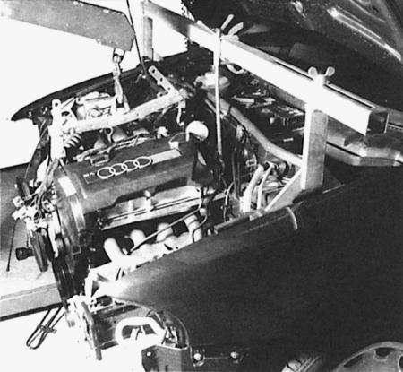
In the workshop, the engine is removed using such a lifting device. It is for this purpose that the cylinder head has mounting eyes, to which, of course, chains or cables can be attached. Before it is removed, the front part of the car must be removed and all plug and screw connections must be disconnected.
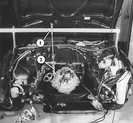
On the dismantled engine, you can see the so-called interceptor device (1), which is combined with the gearbox bracket (2). The purpose of this is to support the gearbox, which could otherwise fall down when the engine is dismantled. Of course, the same effect can be achieved by supporting it from below.
A description of the dismantling of engines of all models would be beyond the scope of this manual. Here are just a few essential points on this topic:
Execution order
1. The engine is lifted upwards without a gearbox. For this you need a pulley system that you can hang securely at a sufficient height. A "preloaded assistant" is also useful.
2. Before starting the actual dismantling, remove all interfering parts of the car: the lower engine lining, the air filter housing, and the front part of the car as a whole. If there is one, dismantle the viscous fan.
3. Since there are many electrical wires and vacuum hoses installed in the Audi A4, you must first mark all these wires and hoses in order to then correctly connect them in the right place.
4. Before disconnecting the battery, you must make sure that you have the anti-theft code for the radio.
5. Disconnect the battery only when the ignition is off, otherwise the control units may be damaged.
6. Before finally disconnecting the engine, you need to support the gearbox or lift it slightly together with the still installed engine. For this purpose, a special tool is used in the workshop, which rests against the fastening edges of the wings.
7. The engine itself has a hanging eye into which a lifting device can be inserted. Make sure it is securely fastened.
Tightening torques
|
Details
|
Tightening torque in Nm
|
|
| All bolts and nuts |
M6
M8 M10 M12 |
10
20 45 60 |
| Intake pipe on the exhaust elbow |
M8
|
25
|
| Air conditioning compressor at the bracket |
M8
|
25
|
| Torque converter at the grip shield |
M8
|
35
|
| Engine support at the point of attachment to the engine |
M10
|
45
|
| Viscous coupling at the bracket |
M10
|
45
|
| Servo pump at the bracket |
M8
|
25
|
| Generator at the suspension |
M8
|
35
|
The text is based on materials from the website: AUDImanual.ru