



Table of contents: Removal ↓ Cars with power steering (servo… ↓ Cars with air conditioning ↓ 5-cylinder engine ↓ Diesel engine ↓ Installation ↓
The engine is removed without the gearbox upwards. The intake and exhaust manifolds, as well as the fuel injection device and generator, remain on the engine. A crane is required to dismantle the engine. Under no circumstances should the engine be removed using a mobile lift, as this may cause damage to the engine.
The bolted connections must be unscrewed from the bottom of the body. To do this, place the car on trestles using a mobile lift. Before starting work in the engine compartment, the body wings must be protected with covers.
Depending on the year of the vehicle and its equipment, electrical wires, low-pressure hoses and coolant hoses may be routed differently. Each of the removed wires and hoses should be pre-marked with adhesive tape.
Removal
Disconnect the ground cable from the battery
Drain the coolant, disconnect the hoses from the cooling system pump.
Remove the radiator.
Note: If the hoses are secured with clamps, the clamps should be cut with side cutters. Use new clamps when installing.
Remove the air filter and cover the carburetor with something to prevent foreign objects from getting into it.
Remove the cooling system hoses from the cylinder head and from the exhaust manifold.
Disconnect the vacuum hoses at the intake manifold and carburetor. Mark the hoses with tape for easier installation.
Disconnect the gas drive, but do not remove the retainer.
Disconnect the cold start wire
Mark the fuel lines on the sump with electrical tape, disconnect them and plug them with suitable plugs. For this, you can use clean bolts of the required diameter.
Disconnect the plug connections of the intake manifold heater and the idle speed cut-off valve. Loosen the cable clamps on the cylinder head cover.
Disconnect the electrical wire and brown vacuum line from the control valve on the carburetor.
Mark and disconnect the electrical wires from the temperature sensor, oil pressure indicator switches, and the generator.
Raise the car with a jack.
Remove the lower engine compartment cover. Unscrew the exhaust pipe on the exhaust manifold and gearbox holder. Lower the exhaust system slightly and hang it on a wire.
Unscrew the clutch slave cylinder on the gearbox and set it aside without opening the hydraulic system.
Caution: Do not unscrew the tube.
Cars with power steering (servo control)
Remove the V-belt, remove the hydraulic pump and set it aside or hang it on a wire from the body. The holders remain screwed to the engine block.
Caution: If air enters the hydraulic system, it must be bled after installation.
Cars with air conditioning
Loosen and remove the compressor drive V-belt.
Loosen the compressor mounting bolts and hang it on the side of the body with the pipelines connected.
Caution: Do not open the air conditioner coolant circuit.
5-cylinder engine
Remove the bumper.
Unscrew the middle bumper support.
Unscrew the crossbar from below.
Diesel engine
Unscrew the direct and return fuel lines on the high-pressure fuel pump (HPFP).
Disconnect the electrical wires from the fuel shut-off valve and glow plugs.
Unscrew the exhaust pipe from the exhaust manifold.
Remove the starter.
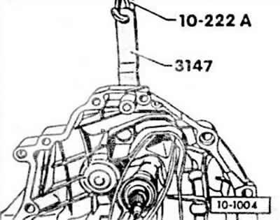
Catch the gearbox with the crossbar V.A.G.-10 222A and 3147. To do this, insert the 3147 clamp into the upper hole of the gearbox engine mount.
Note: If there is no VAG crossmember, place a lift with a wooden pad under the gearbox and slightly lift the gearbox.
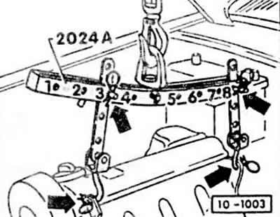
Install the crossbar as shown in the figure, hooking it onto the special earrings -arrows-. Belt pulley side: the 3rd hole in the bar is in position 3. Flywheel side: the 3rd hole in the bar is in position 3. Secure the pins with cotter pins. The figure shows a 4-cylinder engine. With a 5-cylinder engine: on the belt pulley side, the 1st hole in the bar is in position 3, on the flywheel side, the 4th hole in the bar is in position 8.
Note: To align with the center of gravity, the hook bars must be set correctly in length and height. The side of the crossbar with the markings 1-4 faces the belt pulley. The hole in the bars is counted from the beginning of the hooks.
If there is no crossbar for lifting, attach a suitable chain to the special earrings.
Raise the engine with a crane until the engine mounts are unloaded.
Tighten the gearbox lifting device.
Unscrew the engine mounts on the left and right by unscrewing the self-locking nuts.
Unscrew the front engine brackets.
Remove the engine-gearbox connection bolts.
Unscrew the flywheel cover.
Use a crowbar to pry the engine away from the gearbox.
Attention: On cars with an automatic transmission, first unscrew the torque converter from the driven disk, secured with 3 bolts, and its safety device to prevent it from falling out.
Check that all drives and hoses from the engine to the body are disconnected. Then remove the engine.
Attention: Raise the engine carefully to avoid damaging the body.
Installation
Check engine mounts, coolant hoses, oil and fuel hoses for porosity and cracks. Replace if necessary.
Check the clutch disc for sufficient thickness of the friction linings and check their condition. If the linings wear out progressively or the mileage is high, replace the clutch. If the clutch release bearing makes noise when you press the clutch pedal, the bearing must be replaced.
Clean and lightly lubricate with MoS₂ grease the clutch release bearing and the gear engagement of the gearbox input shaft.
Caution: Do not lubricate the clutch release bearing guide sleeve.
Check if there are bushings in the cylinder block for centering the engine and gearbox. If necessary, insert the bushings.
Place a gasket on the bushings and secure it with thick grease at several points on the cylinder block.
Carefully lower the engine into the engine compartment, being careful not to damage the gearbox input shaft, clutch or body.
Screw on the new self-locking engine mount nuts without tightening them.
Tighten the bolts connecting the engine and gearbox.
Screw on the flywheel cover with a torque of 10 Nm.
Tighten the engine brackets with a torque of 25 Nm.
Using rocking movements, seat the engine without tension. Then tighten the engine mounts with a force of 35 Nm.
5-cylinder engine: Screw the cross member from below. Screw the middle part of the bumper. Install the front bumper.
Screw the exhaust pipe onto the manifold with a force of 30 Nm, onto the gearbox holder with a force of 25 Nm.
Install the starter.
Install and tighten the mounting bolts for the cooling compressor and power steering pump, if they were removed. Tightening forces are as follows: compressor supports to the cylinder block, M8 bolts - 25 Nm; m10 bolts - 30 Nm; pump - 20 Nm. Put on and tighten the V-belt.
Install the lower engine compartment cover.
Lower the car.
Connect the electrical wires of the intake manifold heater and the idle air cut-off valve.
Install the electrical wire and brown vacuum line to the control valve
Install the vacuum hoses to the intake manifold and carburetor according to the marks applied. Secure the clamps if necessary.
Connect the gas drive.
Connect the cold start actuator and adjust.
Install the fuel lines on the sump in accordance with the marks applied and secure with clamps.
Connect the electrical wires to the temperature sensor, oil pressure switch sensor and generator.
Install all cooling system hoses and secure with clamps.
Check that all electrical wires, vacuum lines, cooling system circuits and fuel hoses are connected in accordance with the marks applied. Secure the electrical wires with cable ties.
Install the radiator.
Diesel engine:
Screw the direct and return fuel lines to the high-pressure fuel pump. Do not mix up the hollow bolts. The bolt for returning the fuel line is marked "OUT" on the hex head. Reverse connection leads to the following problems: insufficient engine power, foggy exhaust at full load, maximum speed is not reached, the engine runs unevenly at idle.
Adjust the cold start control actuator.
Connect the electrical wires to the fuel shut-off valve and glow plugs.
Check the moment the high pressure fuel pump starts to feed.
Check the oil level in the engine and gearbox.