
Table of contents: Too low pressure readings ↓ Troubleshooting ↓ Pressure loss test (for tightness) ↓ Engine scrolling ↓ Setting cylinder #1 to top dead… ↓ Removal the engine lining ↓ Removal the V-ribbed belt lining ↓ Removal the cylinder head cover ↓
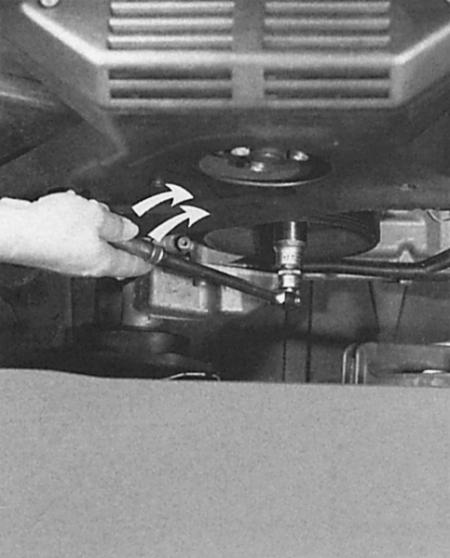
The crankshaft of a six-cylinder engine is turned by the central bolt of the crankshaft belt pulley. The tool to use is a socket wrench with an internal twelve-sided socket SW 24 with a ratchet or lever.
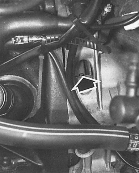
Top dead center (TDC) is found when the "O" mark on the flywheel is below the base edge on the gearbox housing (arrow).
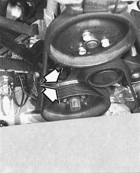
Another TDC marking is located in a six-cylinder engine on the timing belt pulley or on the lower timing belt cover (arrows).
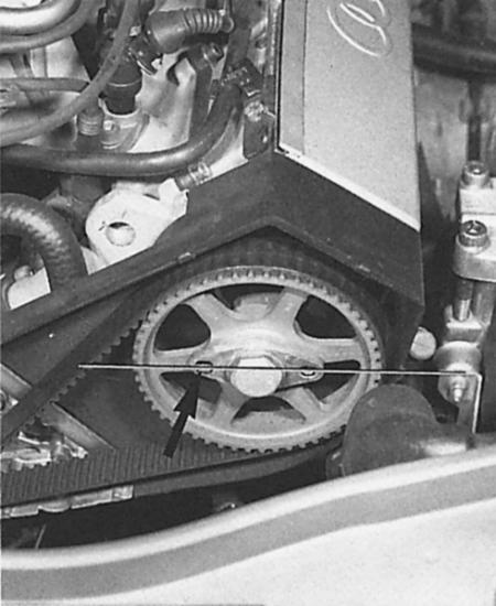
When cylinder No.1 is at TDC, the large holes in the locking plates on both camshaft flywheels face the center of the engine (arrow).
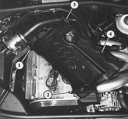
The 1.8L engine trim is secured on the right with two clamps (1 and 2). On the left, the trim is placed on two mounting pins in two places (3 and 4)
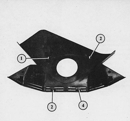
The cover of the poly V-belt of the six-cylinder engine is put on at the bottom on two pins (1 and 2), at the top it is screwed in two places (3 and 4).
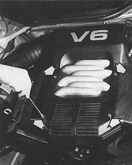
The arrows indicate four quick-release latches that must be turned 90° to the left when removing the six-cylinder engine trim.
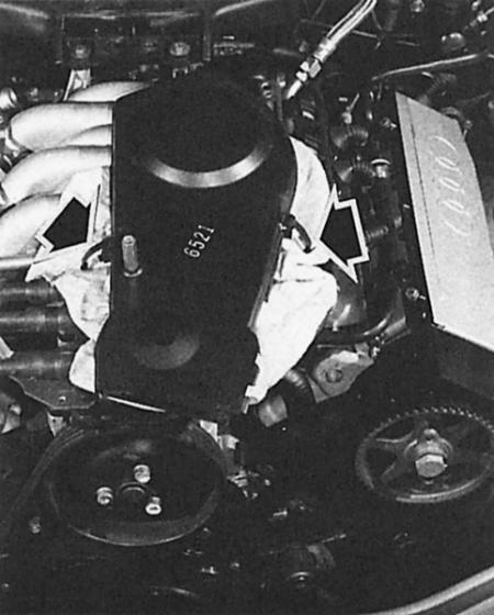
In a six-cylinder engine, the timing belt cover is secured with two clamps (arrows). To remove the right timing belt cover, you must also remove the poly V-belt tension roller (large Allen bolt).
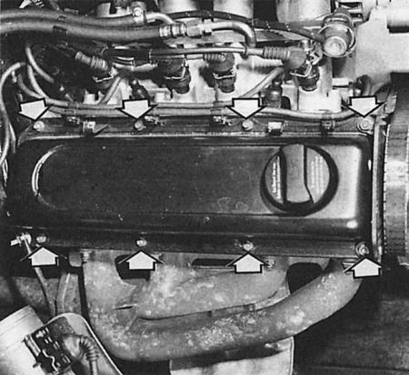
The arrows show the mounting bolts on the cylinder head cover of the 1.6-liter engine. The bolts become accessible only after removing the engine trim.
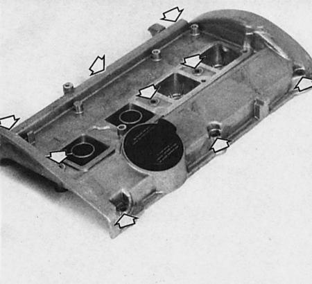
Here the cylinder head cover of a 1.8 liter engine has been removed. The arrows indicate the position of the mounting bolts.
Too low pressure readings
Low compression pressure readings are not a cause for concern; the reason for low readings may be measurement tolerances, which are different for different devices. But if the difference in measurements on different cylinders is more than 3 bar, it is worth thinking about. This may mean the following:
- wear of pistons and piston rings;
- piston rings tightly seated in the grooves as a result of contamination;
- non-circular cylinders as a result of piston seizure;
- deposits on valve stems or valve seats due to combustion products and lubrication;
- burnt valves. In most cases, the cause of insufficient compression pressure is leaky valves and, consequently, reduced engine power. Only a cylinder head repair can help.
Troubleshooting
To localize the defect when the compression pressure is too low, use the following method: using a hand oiler, drip a little motor oil into the spark plug socket and measure the compression pressure again.
- If the readings are still below normal, the valves are not in order.
- If the readings are higher, the problem is in the piston rings and perhaps in the cylinders. The oil that was poured in briefly acted as a gasket between the piston and the cylinder walls, so that the compressed gas had almost no way out.
Pressure loss test (for tightness)
More accurate results are provided by a leak test, which some workshops can perform. If the combustion chamber being tested loses pressure, this is shown on the tester scale.
A larger leak location can be determined by listening:
- A hissing sound from the exhaust pipe indicates that the exhaust valve is not closing tightly.
- Air leaking from the air filter housing indicates a defective intake valve.
- If the cylinder head gasket is faulty or the cylinder head is cracked, compressed air will leak out through the adjacent spark plug hole or from the open coolant expansion tank.
- Worn cylinder walls, piston guides or piston rings allow pressure to leak into the crankcase and out the open oil filler neck or dipstick tube.
Engine scrolling
1. To do this, park a car with a manual transmission in fourth gear on a level surface.
2. In a four-cylinder engine, fit the SW-24 offset wrench to the center nut of the alternator belt pulley and now turn the engine using the V-ribbed belt.
3. In a six-cylinder engine, remove the lower trim of the engine compartment (chapter Body parts), fit a SW 24 socket wrench to the central bolt of the crankshaft belt pulley and turn it using a ratchet or lever.
4. Never rotate the engine by the camshaft timing belt pulley mounting bolt with the timing belt cover removed! The timing belt may jump – risk of engine damage.
Setting cylinder #1 to top dead center of ignition timing
In a four-stroke engine, the piston reaches the top dead center (TDC) twice during the four working strokes: once during the ignition of the inlet mixture, and the second time after the exhaust gases are ejected, with the intake of the fuel-air mixture beginning immediately after that. Usually, the TDC position of cylinder No.1 is required for various adjustments.
1. Four-cylinder engine: remove the timing belt cover (described in this chapter above). Turn the crankshaft so that the mark on the camshaft timing belt pulley is aligned with the corresponding mark on the cylinder head cover or on the rear timing belt cover.
2. For greater accuracy, move the crankshaft back and forth a little so that the inspection hole on the left in the gearbox bell (hard to reach) the "O" marking on the flywheel is positioned opposite the edge of the inspection hole.
3. Six-cylinder engine: remove the timing belt cover on the right and left (described in the chapter below).
4. Rotate the crankshaft until the large holes in the retaining plates of both camshaft pulleys are aligned on the inside against each other.
5. If necessary, move the crankshaft back and forth a little or turn it towards you so that the "O" mark on the flywheel in the inspection hole of the gearbox bell is opposite the edge of the inspection hole.
Removal the engine lining
1. 1.6L 4-cylinder engine: Using a large screwdriver, turn the two quick-release fasteners 90° to the left. Unhook and remove the trim.
2. 1.8L 4-cylinder engine: Loosen the two retaining clips on the right side of the trim. Pull the trim out of the left hook and remove.
3. Lift the trim upwards at the rear edge above the injection valves and pull it out of the plug connection at the front.
4. Six-cylinder engine: Use a large screwdriver to turn the four quick-release fasteners 90° to the left.
5. Remove the trim.
Removal the V-ribbed belt lining
6-cylinder engine
The poly V-belt in a six-cylinder engine runs under the trim on the front side of the engine.
1. Remove the engine cover.
2. Loosen the two Allen bolts near the ignition coil pack.
3. Remove the trim upwards from both mounting bolts.
4. When installing, first place the cladding on the fastening pins.
Removal the cylinder head cover
1. 1.6L engine: remove the retaining clamp, remove the crankcase ventilation hose.
2. Remove the engine cover as described above.
3. If necessary, remove the cable harness from the clamps.
4. Loosen the mounting nuts.
5. Remove the reinforcing strips (together with brackets of high voltage wire).
6. Remove the rear timing belt cover.
7. Lift the lid.
8. If necessary, remove the oil deflector.
9. Four-cylinder engine with a displacement of 1.8 liters: remove the engine cover as described.
10. Remove the ignition coils (chapter Ignition system).
11. Loosen the nine cylinder head cover mounting bolts.
12. Lift the lid.
13. If necessary, remove the oil deflector.
14. Six-cylinder engine: remove the engine cover.
15. Loosen the mounting bolts.
16. Lift the lid.
17. If necessary, remove the oil deflector.
18. When installing, use a new gasket if possible.
19. 1.6L 4-cylinder engine: Don't forget the shield reinforcement bar under the mounting nuts.
20. 1.8L 4-cylinder engine: Check the two-piece gasket for proper fit.
21. Six-cylinder engine: Lightly lubricate the inside and outside of the cylinder head cover gasket with silicone grease D 007 000 04 (from spare parts).
22. Apply a small amount of Silimate AMV 174 004 01 from the Audi Parts Warehouse to all four edges between the cylinder head sealing surface and the camshaft bearing cap. Make sure that the grease hole under the camshaft bearing cap does not become clogged.
23. For all models: Starting from the middle of the cover, tighten the nuts and bolts crosswise to a tightening torque of 10 Nm.
The original text is available on the website AUDIMANUAL.ru