
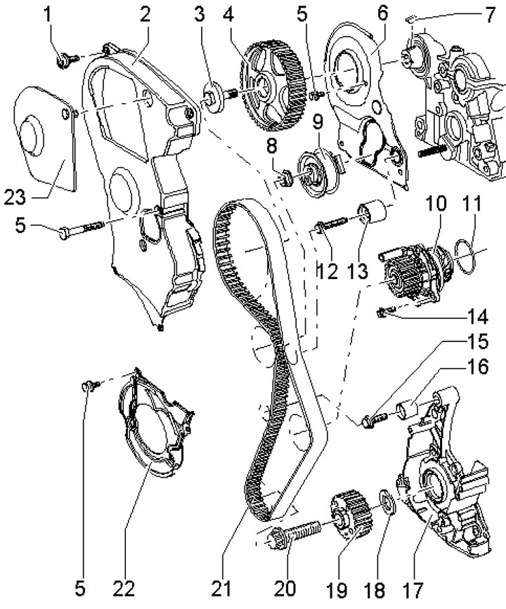
22.1. Timing Belt Installation Details 1. Cover fastening bolts 2, 10 Nm; 2. Upper timing belt cover; 3. Wheel mounting bolt 4, 50 Nm, then tighten to an angle of 180°; 4. Camshaft gear wheel; 5. Cover mounting bolts 2, 10 Nm, apply varnish to the threads; 6. Rear timing belt cover; 7. Segment key; 8. Roller fastening nut 9, 25 Nm; 9. Roller of the semi-automatic timing belt tensioner; 10. Water pump; 11. Sealing ring, subject to replacement; 12. Roller mounting bolt 13, 25 Nm; 13. Intermediate roller; 14. Pump mounting bolts 10, 15 Nm; 15. Roller mounting bolt 16, 35 Nm; 16. Intermediate roller; 17. Front crankshaft oil seal housing; 18. Washer (diamond coated) wheels 19, subject to replacement; 19. Crankshaft gear; 20. Wheel mounting bolt 19, 90 Nm, then tighten to an angle of 90°, use a new bolt; 21. Timing belt; 22. Lower timing belt cover; 23. Cover plate 2
2. Remove the engine top cover as shown in the illustration 17.10. Open the cap of the expansion tank of the cooling system.
3. On models with independent/additional heating, remove the screw (1 in illustration 5.4) its exhaust pipe on a sound-insulating casing.
4. Unscrew the fasteners (1 and 2 in Illustration 5.5) and remove the front soundproofing screen.
5. Drain the coolant (see Chapter 3).
6. Set the radiator frame to the service position (see Section 18).
7. Disconnect the coolant pipe (see illustration).
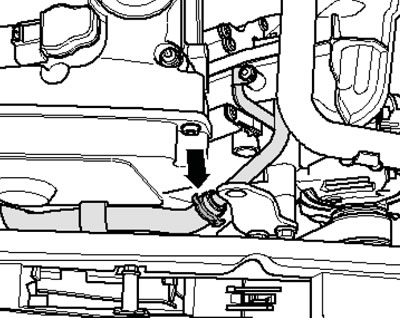
22.7. Coolant pipe connection
8. Mark the alternator belt with chalk or a felt-tip pen to indicate the direction of rotation so that you can install the belt in the same way. Loosen the belt tension by turning the tensioner in the direction of the arrow (see illustration 17.18). Secure the tensioner with clamp No. T40098 and remove the alternator belt.
9. Turn the crankshaft clockwise by the central bolt until the marks on the crankshaft pulley and on the camshaft gear coincide with the TDC marks (see illustration).
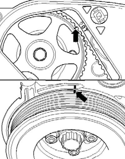
22.9. VM TagsT
10. Holding the crankshaft from turning by the central bolt, unscrew the four bolts (3 in illustration 19.1) and remove the pulley.
11. Remove the bolts securing the lower timing belt cover (see illustration).
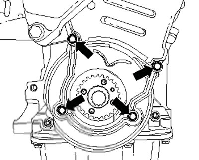
22.11. Timing belt lower cover mounting bolts
12. Remove the remaining bolts securing the upper timing belt cover (see illustration) and remove the engine cover.
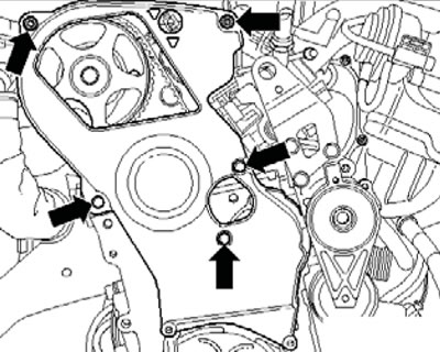
22.12. Upper timing belt cover mounting bolts
13. Mark the direction of the timing belt with chalk or a felt-tip pen so that you can install the belt in the same way later. Loosen the tensioner roller mounting nut and remove the timing belt. Turn the crankshaft slightly counterclockwise.
Note: When the timing belt is removed, no piston should be at TDC when turning the camshaft, otherwise the piston or valves may be damaged. When installing the timing belt, the engine should be warm to the touch.
14. Place the timing belt on the crankshaft sprocket. If using a used belt, observe the direction of its movement.
15. Secure the lower timing belt cover with the two lower bolts, install the crankshaft pulley and tighten the new crankshaft pulley mounting bolts.
16. Turn the crankshaft clockwise by the central bolt until the marks on the crankshaft pulley and on the camshaft gear coincide with the TDC marks (see illustration 22.9).
17. Place the timing belt on the pulleys and gears in the following sequence: tensioner pulley → camshaft gear → water pump gear → idler pulley (13 in illustration 22.1).
18. Make sure that the tensioner roller is correctly installed in the cylinder head (see illustration).
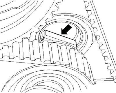
22.18 Tensioner roller position
19. Tighten the timing belt by turning the eccentric to the right with a rod wrench (arrow on the illustration), until the notch is positioned over the toe. Then loosen the timing belt again and tighten it until the notch and toe are opposite each other. Tighten the tensioner pulley mounting nut.
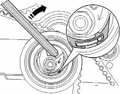
22.19. Tensioning the timing belt
20. Turn the crankshaft 2 turns clockwise, again setting the piston of the 1st cylinder to the TDC position (see illustration 22.9). It is important that the last 45° of rotation be completed without stopping.
21. Check the timing belt tension again: the toe and the notch should be opposite each other (see illustration 22.19). Check the timing phases again and, if necessary, repeat the adjustment by returning to paragraph 14.
22. Further installation is carried out in the reverse order of dismantling the components. Use new crankshaft pulley mounting bolts. Install the timing belt cover mounting bolts on thread varnish.
(The original material is located on the website: AUDIMANUAL.ru)