
Note: When replacing the cylinder head or head gasket, drain the old coolant and fill it with new coolant.
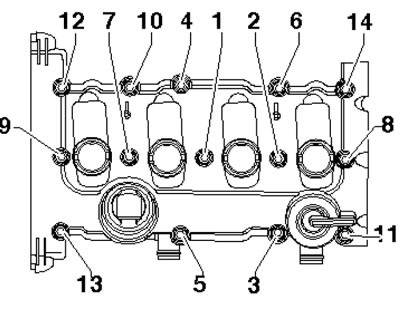
1. The details of the cylinder head and its cover installation are shown in the illustration.
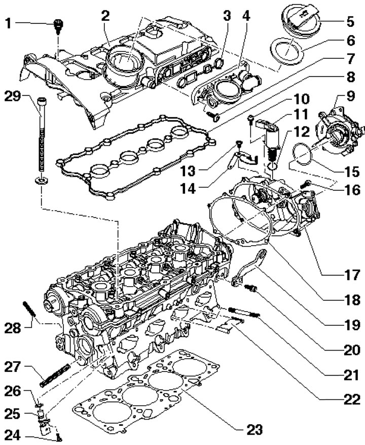
25.1. Cylinder head and cover installation details1. Cover fastening bolts 2, 10 Nm; 2. Cylinder head cover; 3. Valve box gasket 4; 4. Valve box; 5. Oil filler cap; 6. Cover sealing ring 5; 7. Valve box mounting bolts 4.4 Nm; 8. Cover gasket 2; 9. Vacuum pump; 10. Valve mounting bolts 11; 11. Valve No.1 for adjusting the timing phases; 12. Sealing ring, subject to replacement; 13. Bracket mounting bolt 14, 10 Nm; 14. Electrical wiring bracket; 15. Sealing ring; 16. Housing fastening bolts 17; 17. Timing phase adjustment mechanism housing; 18. Housing gasket 17, subject to replacement; 19. Engine lifting eye; 20. Lifting eye mounting bolt, 25 Nm; 21. Intake manifold studs, 10 Nm; 22. Jumper; 23. Cylinder head gasket, subject to replacement; 24. Bolt for fastening the CMP sensor 25, 10 Nm; 25. SMR sensor; 26. Sealing ring; 27. Tensioner roller stud, 10 Nm; 28. Exhaust manifold studs, 20 Nm; 29. Cylinder head mounting bolts, 40 Nm, then tighten to an angle of 180°, use new bolts
Cylinder head cover
2. Remove the engine top cover as shown in the illustration 17.10.
3. Remove the two upper timing belt upper cover mounting bolts (see illustration 22.12).
4. Unscrew the bolts (similar to No.1 in the illustration13.8), disconnect the ignition coil connectors (2) and release the electrical wiring.
5. Remove the ignition coils (2 in the illustration) in an upward direction.
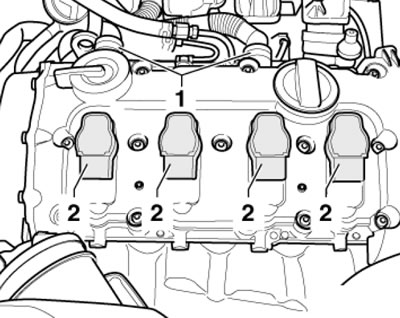
25.5. Ignition coils (2) and hoses (1)
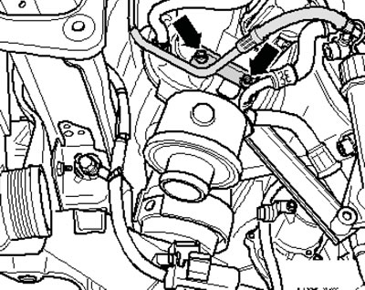
6. Disconnect the EVAP line from the cylinder head cover (1 in the illustration), unscrew the screws (arrows) and remove the valve box from the cylinder head cover.
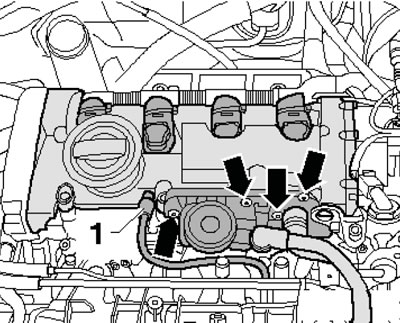
25.6. EVAP Hose (1) and Valve Box Fasteners
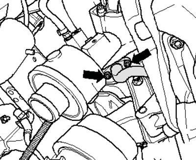
7. Remove the screw (1 in the illustration) and disconnect the PCV tube from the turbocharger, disconnect the EVAP line (2) from the cylinder head cover going to the turbocharger.
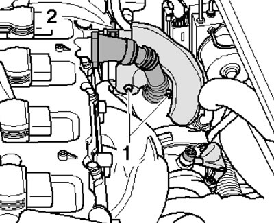
25.7 PCV tube (1) and EVAP line
8. Remove the cylinder head cover mounting screws (see illustration 25.9), starting from the edges to the center and remove it.
9. Installation is performed in the reverse order of component dismantling. A damaged cylinder head cover gasket should be replaced. Tighten the cylinder head cover mounting bolts in the following sequence: (1-14 in the illustration).
25.9. Cylinder head cover fastener tightening sequence
Cylinder head
Note: The plastic spacers included in the repair kit for protecting open valves may be removed immediately before installing the cylinder head. The gasket should also be removed from the packaging immediately before installation. When installing a new cylinder head with the camshafts installed, the mating surfaces between the rocker arms and the camshaft cover must be lubricated with engine oil.
10. Remove the top engine cover as shown in the illustration 17.10. Remove the cap from the engine cooling system expansion tank.
11. On models with independent/additional heating, remove the screw (1 in illustration 5.4) its exhaust pipe on a sound-insulating casing.
12. Unscrew the fasteners (1 and 2 in Illustration 5.5) and remove the front soundproofing screen.
13. Drain the coolant (see Chapter 3) and remove the timing belt (see Section 22).
14. Loosen the camshaft gear mounting bolt, holding the shaft from turning with tool No.3036 (see illustration).
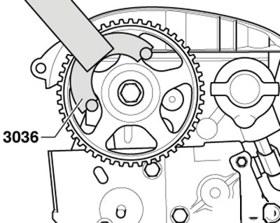
25.14. Keeping the camshaft from turning
15. Remove the gear wheel using puller No. T4001 with jaws No. T4001/6 and No. T4001/7 (see illustration).
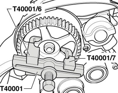
25.15. Removing the gear wheel
16. Remove the bolts (see illustration) and remove the rear timing belt cover.
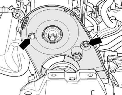
25.16. Timing Belt Rear Cover Fastening Bolts
17. Perform the actions described in paragraphs 20-22, 7 and 32 Section 17.
18. Remove the turbocharger oil line mounting bolt to the engine and the turbocharger support bolt (2).
25.18. Turbocharger oil line and mounting bolt
19. Remove the bolts (see illustration) and disconnect the turbocharger oil feed line.
25.19. Turbocharger oil supply line
20. Remove the bolts (see illustration) and disconnect the turbocharger oil return line.
25.20. Turbocharger oil return line
21. Loosen the bolt (see illustration) turbocharger support by 2 turns. Remove the exhaust pipe and catalytic converter (see Chapter 4), remove the cylinder head cover (see subsection above).
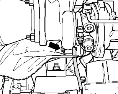
25.21. Turbocharger support bolt
22. Remove the cylinder head bolts in the sequence shown in the illustration. Make sure that all hoses and wires between the engine, body and transmission are disconnected. The following describes how to install the cylinder head.
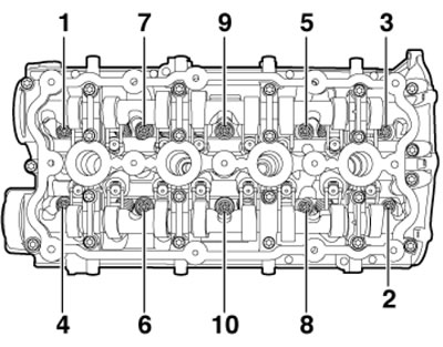
25.22. Sequence of unscrewing the cylinder head mounting bolts
23. Prepare new cylinder head bolts, self-locking nuts, torque bolts, sealing rings and gaskets.
24. Carefully remove any remaining sealant from the cylinder head and block, avoiding the formation of long scratches or burrs. Carefully remove any remaining sandpaper or grinding material used to remove the sealant. Make sure there is no oil or coolant in the blind holes for the cylinder head bolts.
25. Turning the crankshaft by the central bolt, align the mark on the camshaft gear with the mark on the timing belt protective cover. Notches (arrows in the illustration) should stand vertically opposite each other. If the crankshaft has been turned, set the piston of the 1st cylinder to the TDC position and turn the crankshaft back slightly again.
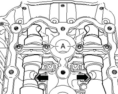
25.25. Installation position of camshafts
26. Remove the new cylinder head gasket from the packaging and place it on the cylinder block along the centering bushings. Handle the gasket carefully, as damage to the silicone layer and corrugated connections will result in loss of sealing.
27. Place the cylinder head on the cylinder block and tighten the new bolts by hand. Tighten the cylinder head bolts in the sequence shown in the illustration to 40 Nm, then tighten them to an angle of 180°.
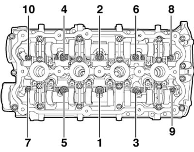
25.27. Cylinder head bolt tightening sequence
28. Install the cylinder head cover, timing belt and alternator belt, install the exhaust pipe.
29. Further installation is carried out in the reverse order of dismantling the components. Finally, check the engine oil level and fill the coolant.
Note: Reusing drained coolant is only permitted if the cylinder head or cylinder block has not been replaced.
Valve No.1 of the timing phase change
30. Remove the top engine cover as shown in Illustration 17.10.
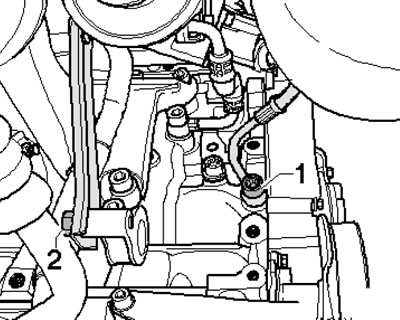
31. Disconnect the connector (1 in the illustration), unscrew the bolts of the electrical wiring holder.
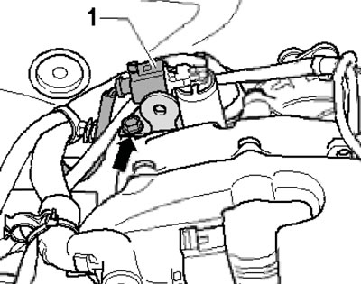
25.31. Timing phase change valve connector (1)
32. Remove the bolts (see illustration) and remove the timing valve from the housing.
Note: Do not pull the valve by the connector.
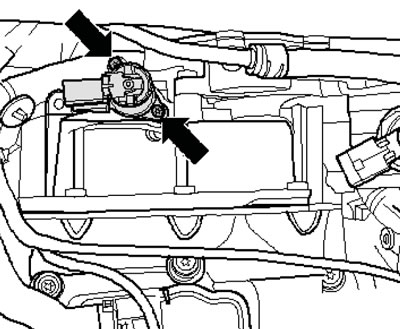
25.32. Fastening of the valve of change of timing phases
33. Make sure that there is no dirt on the valve and in its body. Remove the new valve from the packaging immediately before installation.
34. Moisten the new valve sealing ring with engine oil and insert the valve with the sealing ring into the housing. Press the valve by hand until it stops without tilting it, do not knock on the valve.
35. Tighten the valve fastener to 4 Nm, secure the wiring holder and connect the valve wiring connector.
36. Install the engine cover.