
2.0 TFSI engines
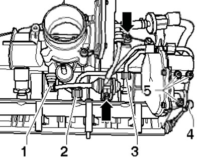
1. The installation details of the fuel distribution line and injectors are shown in the illustration.

5.1. Fuel distribution line and injector installation details 1. Radial compensating element; 2. Injector with sealing rings; 3. Support ring; 4. Fuel distribution line; 5. Fuel pressure sensor, 22 Nm; 6. Fuel pressure sensor in the low-pressure circuit, 15 Nm; 7. Fuel pressure control valve; 8. Mechanical single-plunger injection pump; 9. EVAP canister purge solenoid valve; 10. Throttle body; 11. IAT sensor #2, 5 Nm; 12. Intake manifold mounting bolts, 9 Nm; 13. Inlet manifold
2. Remove the intake manifold (see Section 4). If only the injectors need to be removed, proceed to paragraph 6.
3. Remove the hoses from the carbon adsorber. To do this, loosen the clamp (1 in the illustration) and remove the two bolts (arrows) from the fuel distribution line.

5.3. Fastening the hoses to the EVAP canister
4. Disconnect the fuel lines (2 and 3 in the illustration), carefully push the rod away from the activator (4) of the intake manifold flap and unscrew the bolts (5) securing the activator.
5.4. Removing the intake manifold flap assembly
5. Press the fuel rail through the retaining tabs (arrows in the illustration) on the intake manifold and pull it out of the intake manifold.
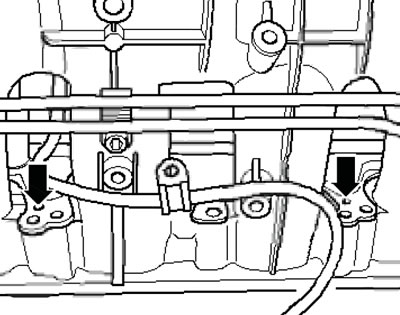
5.5. Removing the fuel distribution line
6. To remove the injectors from the fuel rail, simply pull them out.
7. If the injectors remain in the cylinder head, use special pullers (see illustration).
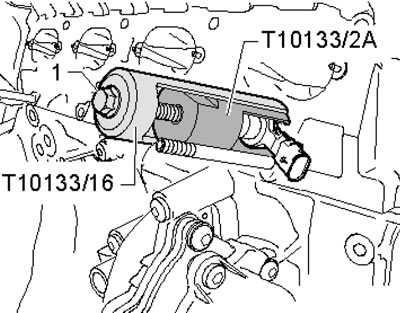
5.7. Removing the injector from the cylinder head
8. The injector installation details are shown in the illustration.
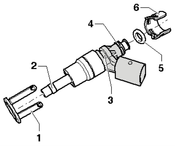
5.8. Injector installation details 1. Radial compensating element (if damaged, subject to replacement); 2. Teflon combustion chamber seal (subject to replacement, not lubricated before installation); 3. Groove in the injector; 4. Spacer (if damaged, subject to replacement); 5. Sealing ring (subject to replacement, lightly lubricated with engine oil before installation); 6. Fuel distribution line support ring
9. Installation is carried out in the reverse order of dismantling the components.
Engines 1.8 l
10. The details of the installation of the fuel distribution line and injectors are shown in the illustration.
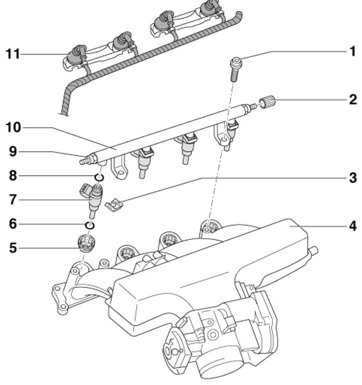
5.10. Details of installation of fuel distribution line and injectors 1. Bolt, 10 Nm; 2. Protective cap; 3. Holder; 4. Inlet manifold; 5. Spacer for injector, 3 Nm; 6, 8. Sealing ring, subject to replacement; 7. Injector; 9. Fuel supply pipe nipple, 25 Nm; 10. Fuel distribution line; 11. Injector connectors
11. Disconnect the connectors of the injectors, IAT sensor, CMP sensor and throttle actuator. Move the wiring to the side.
12. Remove the fuel distribution line mounting bolts.
13. To remove the fuel distribution line, disconnect the fuel lines from it.
14. Remove the holders and remove the injectors.
15. Installation is carried out in the reverse order. Use new sealing rings.
Engines 3.2 l
16. Details of the installation of the fuel distribution line and injectors are shown in the illustration 4.23b.
[This publication is borrowed from the resource «AudiManual.ru»]