
Fuel distribution line with injectors
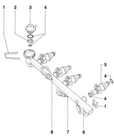
- 1 locking bracket. Follow the correct position on the injector and highway.
- 2 mesh
- 3 fuel pressure regulator
- 4 O-ring. Replace if damaged
- 5 injector
- 6 fuel distribution line
- 7 fuel return connection
- 8 fuel supply connection
Withdrawal
1. Disconnect the vacuum hose and disconnect the switch valve connector at the intake manifold. Remove the spark plug connectors.
2. Loosen the hexagon socket screws (indicated by arrows) and deflect the top of the intake manifold.
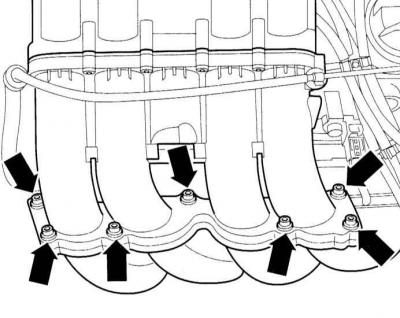
Warning: The illustration shows a 1.8L engine.
3. Disconnect the vacuum hose from the fuel pressure regulator.
Warning: The fuel system is under pressure! When opening the system, fuel may escape, collect it with a rag. Use protective goggles when doing this. Do not smoke, do not use naked flames, risk of fire! Keep a fire extinguisher ready.
4. Disconnect the pressure pipe from the fuel distributive highway, at the same time collect the following fuel with a rag.
5. Disconnect the connector to the injectors.
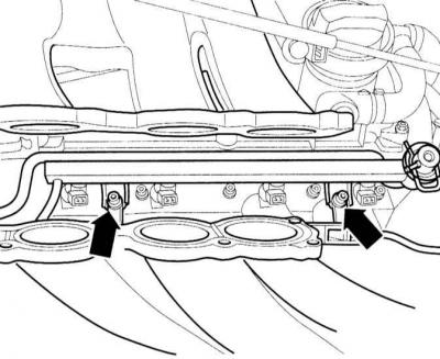
6. Turn out bolts of fastening of a fuel distributive highway and take out from a final collector injectors with a fuel distributive highway in a set.
Warning: The illustration shows a 150 hp engine.
7. Remove clips of connection of injectors and the fuel distributive highway. Remove the injectors from the fuel distribution line. The injectors are only inserted but not secured.
Warning: Do not swap injectors, install them in the same place.
Installation
Warning: When reinstalling the injectors, be careful not to damage the O-rings and the injectors in the cylinder head. Be sure to replace sealing rings with new ones. In this case, do not remove the front plastic bushings from the injectors.
8. Lightly lubricate the O-rings with clean engine oil before reinstalling.
9. Insert the injectors vertically as far as they will go into the fuel distribution line and secure with brackets.
10. Carefully insert the line with the injectors into the intake manifold and press it in as far as it will go.
11. Install the mounting bolts, slightly push the fuel distribution line towards the intake manifold with your hands and tighten the bolts to 10 Nm.
12. Connect the plug connections of the injectors.
13. Fix the giving pipeline at the fuel distributive highway.
14. Connect the vacuum line at the pressure regulator.
15. Secure the top of the intake manifold with a new gasket.
16. Connect the vacuum hose and the changeover valve connector at the intake manifold.
17. Connect the spark plug connectors.
Checking the injectors
Fuel injectors are solenoid valves opened and closed by the engine control device, which determines the opening time and duration of fuel injection, depending on the engine speed, throttle position, the amount of incoming air mass, the temperature of the air entering the engine, the temperature of the coolant and the presence of oxygen in the exhaust gases based on information received from sensors installed on and around the engine. Injectors spray fuel in a cone-shaped jet. After spraying fuel, the injector valve does not close tightly, problems may occur when starting a hot engine. If the injectors are faulty, the engine may continue to operate even after the ignition is turned off, in the glow ignition mode.
18. Before checking the injectors, check the condition and operability of the fuse for the engine management system, the crankshaft speed sensor and the fuel pump relay.
Checking the voltage supply to the injectors
19. Disconnect the electrical connector from the first cylinder injector.
20. Connect a control LED to the connector pins. When cranking the crankshaft of the engine with a starter, the LED should flash.
21. Similarly, check the voltage supply to the remaining fuel injectors.
LED does not flash on any of the cylinders
22. Connect the control LED to pin No. 1 of the electrical connector to supply voltage to the injector and vehicle ground. Connect contact No. 2 of the electrical connector to the vehicle ground.
23. Turn the engine crankshaft with the starter. In this case, the LED should flash. Otherwise, check the entire electrical supply circuit of the injectors.
LED does not flash on only one or more cylinders
24. Check the condition of the electrical supply circuit of the injectors, determine and eliminate the place where the electrical circuit is broken or shorted to ground. Also check the operation of the engine control unit.
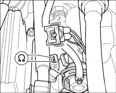
Resistance test

25. Consistently disconnect the electrical connectors from the injectors and, using an ohmmeter, check the resistance of the injectors, which should be in the range from 12 to 17 ohms.
Warning: On an engine warmed up to normal operating temperature, the resistance of the injectors increases by 4 - 6 ohms.
26. If the injector resistance is out of specification, replace it.
Checking the spray jet and the tightness of the injector valve
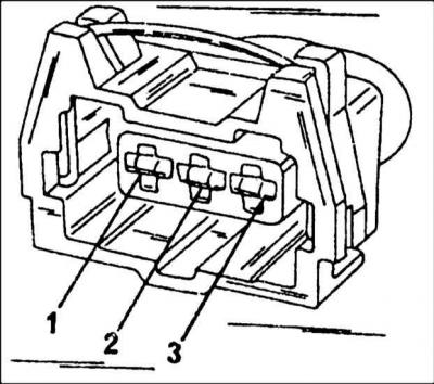
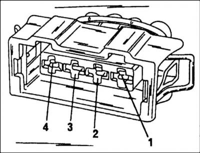
27. Disconnect the four-pin electrical connector from the coolant temperature sensor.
28. Close contacts 1 and 3 of the sensor with a resistance of 15 ohms.
29. Remove a fuel highway together with injectors, without disconnecting fuel hoses from it.
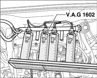
30. Insert injectors into measuring vessels, e.g. VAG 1602.
31. Have an assistant turn the starter on for a few seconds. When the starter is running, the injectors should spray fuel. Check the fuel spray jet, which should be cone-shaped and the same for all injectors.
32. Switch off the ignition and check the tightness of the injectors. Within 1 minute, no more than two drops of fuel should flow out of the injectors.
33. Install the fuel line with the injectors on the engine. Before installation, check the condition and lubricate the O-rings of the injectors.
34. Connect the electrical connector to the coolant temperature sensor.
35. Connect the multi-pin electrical connector to the ignition coil control unit.
36. Install the engine top cover.
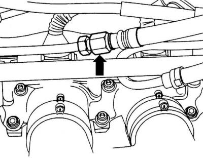
Checking the pressure regulator
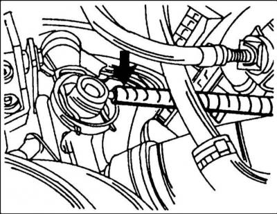
37. For accurate measurement of fuel pressure, a special pressure gauge VAG1318 is used with additional parts, which allows you to measure control values. The idle pressure is 2.5 bar. When the vacuum hose is removed at the point indicated by the arrow, the pressure rises to 3.0 bar. After the engine has stopped, the pressure must be at least 2.3 bar. However, the pressure should drop to 2.0 bar after 10 minutes.
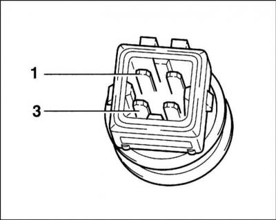
Checking the coolant temperature sensor
38. The sensor performs a dual task. First, it reports the temperature of the coolant in the engine and, second, it connects to a remote thermometer on the instrument panel. Sensor 2 is located on the rear side of the cylinder head. If an air conditioner is installed, the second temperature sensor -1- is in the immediate vicinity. To check, do the following:
39. Remove the sensor plug.
40. Connect an ohmmeter to the two pins of the plug 1 and 3. With a cold engine and at room temperature, the ohmmeter reading should be between 1.5 and 3.0 kΩ. If not, install a new sensor.
Checking the intake air temperature sensor
The sensor is installed only on engines with a turbocharger. The sensor is installed next to the throttle control unit.
41. Remove the sensor plug.
42. Connect an ohmmeter to the sensor terminals. On a cold engine and at room temperature, the resistance should be 1.6 - 2.8 kOhm. Otherwise, replace the sensor.
Checking the intake air mass meter
If there is not sufficient experience in electrical measurements, only the voltage supply to the meter and the connection to the control unit can be checked. Air mass meters on an engine with and without a turbocharger are different. On an engine without a turbocharger, it is integrated into the air filter housing. An LED tester is required to test.
43. Disconnect the plug from the air mass meter.
44. Connect the probes of the LED probe between pin 3 of the plug and "weight".
45. The assistant must turn on the starter (start the engine). If the LED lights up, then voltage is applied to the meter.
46. To check the connections of the control unit, turn off the ignition and remove the plug from the unit. Now you need to check the passage of current.
47. On a non-turbocharger engine plug, connect an ohmmeter between pin 1 on the control unit plug and pin 2 on the air mass meter plug. Also measure the resistance between pin 9 and pin 2. In both cases there should be continuity (0 ohm).
Visitor comments