



Table of contents: 2.0 TFSI engines ↓ Engine 1.8 l ↓ Engine 3.2 l ↓ Diesel engines 1.9 and 2.0 l SOHC ↓ Diesel engines 2.0L DOHC ↓
2.0 TFSI engines
Note: After removing or replacing the intake manifold, the intake manifold flap position sensor must be initialized using diagnostic equipment.
1. The installation details of the intake manifold are shown in the illustration.
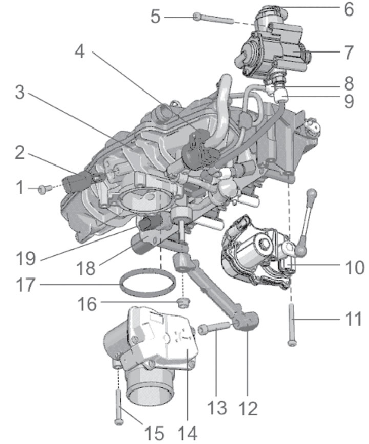
4.1. Intake manifold installation details 1. IAT sensor mounting bolt, 5 Nm; 2. IAT sensor #2; 3. Inlet manifold; 4. Evaporative absorber purge solenoid valve No.1; 5. 3 fuel injection pump mounting bolts 7, 10 Nm; 6. Fuel pressure control valve; 7. Mechanical single-plunger fuel injection pump; 8. Fuel return pipe nipple, 40 Nm, subject to replacement; 9. Fuel supply pipe to the distribution line, 30 Nm; 10. Intake manifold flap actuator; 11. 3 activator mounting bolts 10.7 Nm; 12. Intake manifold support; 13. Support mounting bolt 12, 23 Nm; 14. Throttle actuator; 15. 4 activator mounting bolts 14.7 Nm; 16. Support mounting nut 12, 10 Nm; 17. Sealing ring, subject to replacement; 18. Fuel distribution line; 19. Fuel pressure sensor, 22 Nm
2. Remove the top engine cover (see Chapter 2).
3. If necessary, disconnect any interfering electrical wiring connectors.
4. On AT models, disconnect the vacuum hose between the intake manifold and the vacuum pump on the intake manifold.
5. Disconnect the fuel line (see illustration 17.25 Chapter 2) and collect the leaked fuel.
6. Disconnect the hoses (arrows in the illustration) from the cylinder head, unscrew the two bolts (1 and 2) from the coolant pipe.
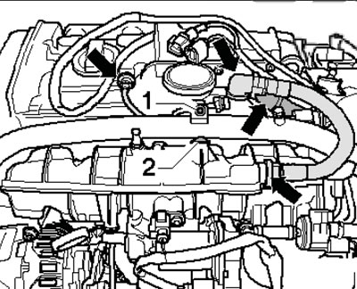
4.6. Cylinder head hose connections
7. Remove the bolts from the oil pipe (1 in the illustration) and coolant pipes (2).
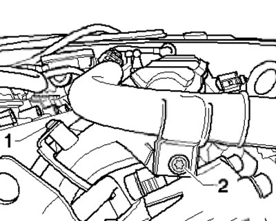
4.7. Fastening the oil pipe and coolant pipe
8. Open both fuel injection pump connections (see illustration), loosen the hose clamps and disconnect the intake hose from the throttle body and intake manifold.
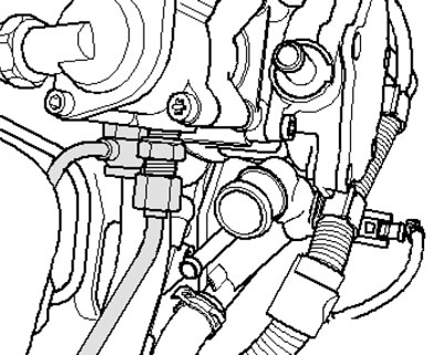
4.8. Fuel injection pump connections
9. Disconnect the connector (1 in the illustration) fuel pressure sensor, pull out the engine oil dipstick and unscrew the dipstick guide tube mounting bolt.
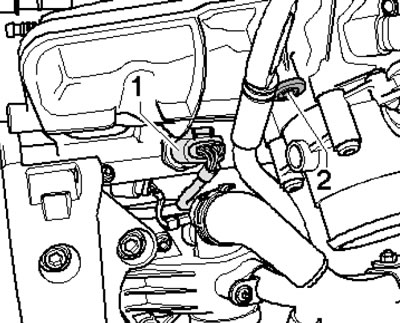
4.9. Fuel pressure sensor connector and dipstick guide tube bolt
10. Unscrew the bolt (1 in the illustration) oil pipe fastenings.
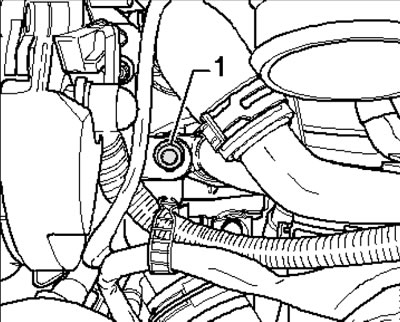
4.10. Oil pipe mounting bolt
11. Unscrew the nut (arrow on the illustration) intake manifold support fastenings (if necessary, remove the throttle body).
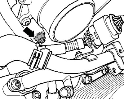
4.11. Intake manifold support mounting nut
12. Separate the feeler gauge guide tube from the hinge (2 in the illustration) and unscrew the bolt (1) on the intake manifold support. Unscrew all the intake manifold mounting bolts and remove it together with the fuel distribution line.
Note: Injectors may remain in the line.
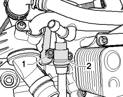
4.12. Intake manifold support mounting bolt
13. Installation is carried out in the reverse order of dismantling the components.
Engine 1.8 l
14. The installation details of the intake manifold are shown in the illustration.
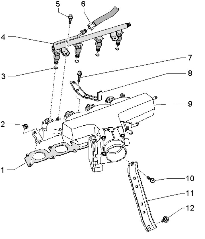
4.14. Intake manifold installation details 1. Gasket, subject to replacement; 2. Nut, 10 Nm; 3. Sealing rings are subject to replacement; 4. Fuel distribution line with injectors; 5. Bolt, 10 Nm; 6. Fuel line, 22 Nm; 7. Bolt, 10 Nm; 8. Bracket of the feeler gauge guide tube; 9. Inlet manifold; 10, 12. Bolt, 23 Nm; 11. Intake manifold support
15. Drain the coolant and remove the upper coolant pipe (see Chapter 3).
16. Disconnect the vacuum hose from the intake manifold (1 in the illustration) and the inlet hose (3), disconnect the connectors (2 and 4).
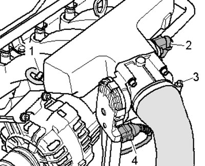
4.16. Intake manifold hoses and connectors
17. Disconnect the vacuum hoses from the intake manifold (see illustration).
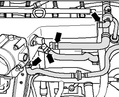
4.17. Vacuum hoses
18. Unscrew the bolt (arrows in the illustration) and remove the mounting plate of the turbocharger air circulation valve (1) and the additional air supply valve (2).
Note: Do not disconnect electrical wiring or vacuum hoses.
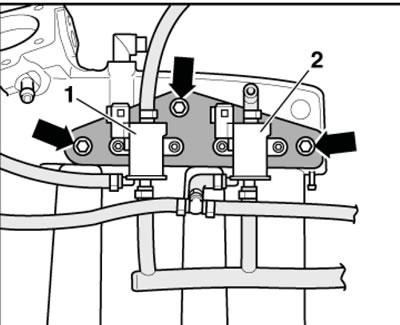
4.18. Mounting plate fastener
19. Unscrew the bolts and remove the intake manifold support (see illustration 31.5 Chapter 2).
20. Disconnect the connector (1 in the illustration) sensor, unscrew the bolts (3) securing the fuel distribution line and remove it together with the injectors (2) from the intake manifold. Place the distribution line on a clean rag in the rear of the engine compartment.
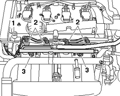
4.20. Electrical wiring connectors
21. Pull out the dipstick (1 in the illustration), release the fastener of its guide, release the fastener of the intake manifold (arrows) and remove it. Plug the intake ports in the cylinder head.
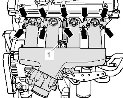
4.21. Fastening the intake manifold
22. Installation is carried out in the reverse order of dismantling the components.
Engine 3.2 l
23. The details of the intake manifold installation are shown in the illustrations.
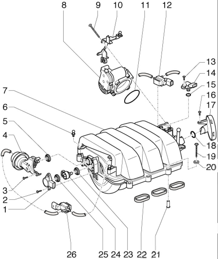
4.23a. Installation details of the upper section of the intake manifold 1. Intake manifold position sensor; 2, 3. Bolt, 2.5 Nm; 4. Intake manifold position switching actuator; 5. Cuff; 6. Ball head stud, 2.5 Nm; 7. Upper section of the intake manifold; 8. Throttle module; 9. Bolt, 5 Nm; 10. Wiring harness bracket; 11, 15, 18. Sealing ring, subject to replacement; 12. Intake manifold flap valve; 13, 16. Bolt, 2.5 Nm; 14. IAT/MAP sensor; 17. PCV pressure control valve; 19. Bolt, 6 Nm; 20. Washer; 21. Bushing; 22. Gaskets; 23, 25. Cuff; 24. Lever with toothed segment; 26. Intake manifold flap switching valve
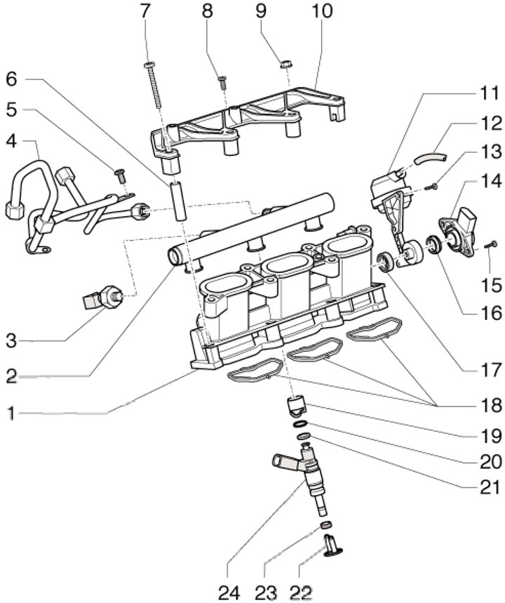
4.23b. Installation details of the lower section of the intake manifold, fuel distribution line and injectors 1. Lower section of the intake manifold; 2. Fuel distribution line; 3. Fuel pressure sensor; 4. High pressure tubes; 5, 7. Bolt, 10 Nm; 6. Bushing; 8. Bolt, 2.5 Nm; 9. Nut, 10 Nm; 10. Fuel distribution line holder; 11. Vacuum block of intake manifold flap drive; 12. Vacuum hose of the intake manifold flap valve; 13, 15. Bolt, 2.5 Nm; 14. Intake manifold flap position sensor; 16, 17. Compaction; 18. Gaskets; 19. Support ring; 20. Sealing ring, subject to replacement; 21. Spacer ring; 22. Radial compensating element; 23. Combustion chamber seal; 24. Injector
Diesel engines 1.9 and 2.0 l SOHC
24. The details of the intake manifold installation are shown in the illustration.
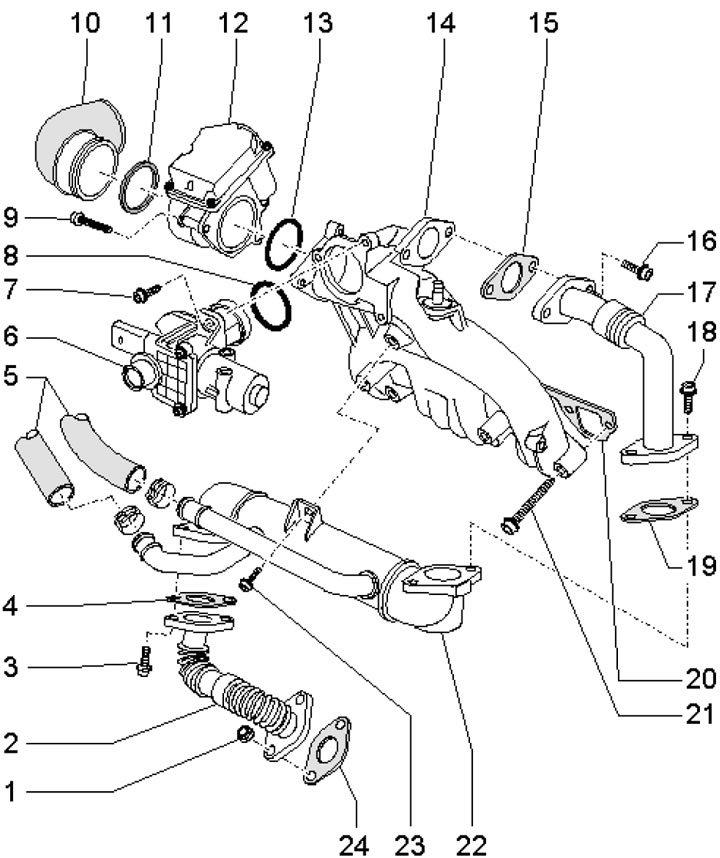
4.24. Installation details of the intake manifold and EGR cooler 1. Nut, 25 Nm, subject to replacement; 2. Lower EGR connection pipe; 3. Bolt, 22 Nm; 4. Gasket, subject to replacement; 5. Coolant hoses; 6. EGR valve with EGR sensor; 7, 9. Bolt, 10 Nm; 8, 13. Sealing ring, subject to replacement; 10. Air hose; 11. Compaction; 12. Connecting the intake manifold to the valve actuator; 14. Inlet manifold; 15, 19, 20, 24. Gasket, subject to replacement; 16, 18. Bolt, 22 Nm; 17. Lower EGR connecting pipe; 21. Bolt, 25 Nm; 22. EGR radiator; 23. Bolt, 10 Nm
25. Drain the coolant (see Chapter 3).
26. Remove the upper engine cover (see Chapter 2) and the insulation underneath. Replace the engine oil dipstick.
27. Disconnect the connector (1 in the illustration), unscrew the bolt (2) and remove the air tube.
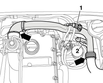
4.27. Connector and air tube on the intake manifold
28. Remove the air cleaner air intake (see Section 16 Chapter 1). Disconnect the connector (1 in the illustration) mAF sensor, loosen the clamp (2) and remove the air supply hose. Move the electrical wiring aside and remove the air cleaner housing.
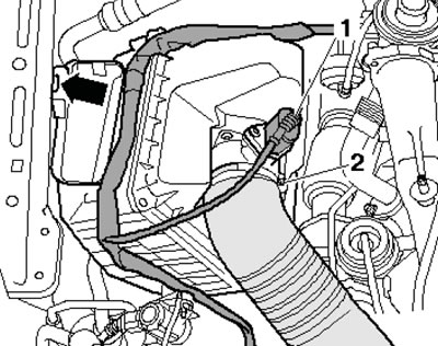
4.28. Removing the air cleaner housing
29. Disconnect the EGR sensor wiring connectors (1 in the illustration) and the intake manifold flap activator (2).
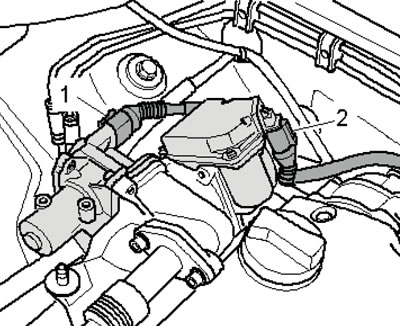
4.29. Electrical wiring connectors
30. Disconnect the air intake hoses (1 in the illustration), loosen the nuts (3), unscrew the bolts (arrows) and remove the intake manifold together with the EGR radiator.
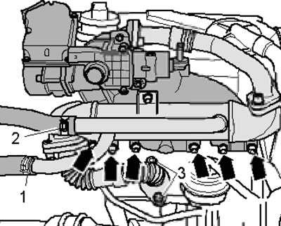
4.30. Removing the intake manifold
31. Installation is carried out in the reverse order of dismantling the components. Use new self-locking nuts and gaskets.
Diesel engines 2.0L DOHC
32. The details of the installation of the intake manifold are shown in the illustration.
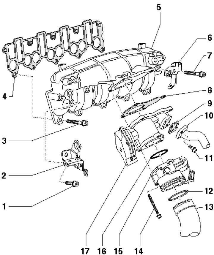
4.32. Intake manifold installation details 1, 3, 7. Bolt, 22 Nm; 2. Lifting eye; 4, 8, 9. Gasket, subject to replacement; 5. Inlet manifold; 6. Bracket; 10. EGR connecting pipe; 11. Bolt, 22 Nm; 12. Compaction; 13. Air supply hose to the intercooler; 14. Bolts, 10 Nm; 15. Intake manifold flap actuator; 16. Sealing ring, subject to replacement; 17. EGR valve
33. All fasteners and connections are accessible after removing the upper decorative engine cover.
(The original publication in its entirety is posted on the website AUDIMANUAL.RU)