
2.0 TFSI engines
1. Turbocharger installation details are shown in the illustrations.
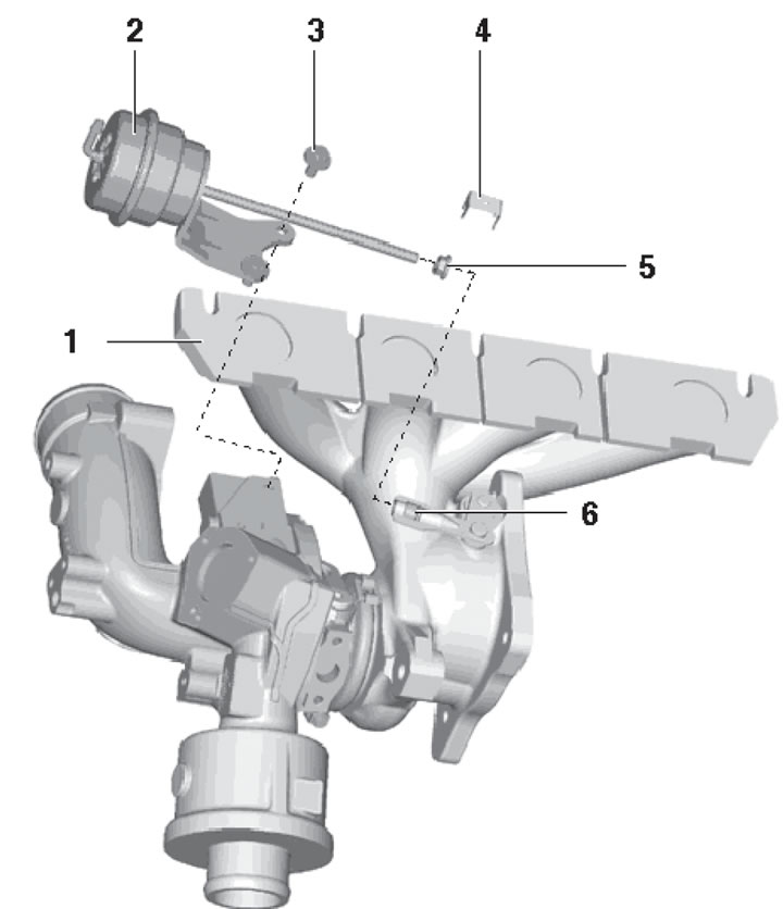
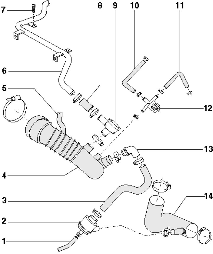
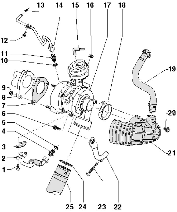
7.1a. Turbocharger Installation Details, Part 1 of 4 1. PCV hose; 2. ACF Line; 3. Turbocharger vacuum module; 4. Gasket, subject to replacement; 5. Nipple; 6, 8. Hose; 7. Bolt, 8 Nm; 9. Bolt, 3 Nm; 10. Solenoid valve for regulating the boost pressure; 11. Hose; 12, 14. Bolt, 7 Nm; 13. Brackets; 15. Turbocharger air circulation valve; 16. Sealing ring, subject to replacement; 17. Turbocharger; 18. Gasket, subject to replacement; 19. Bolt, subject to replacement, 9 Nm
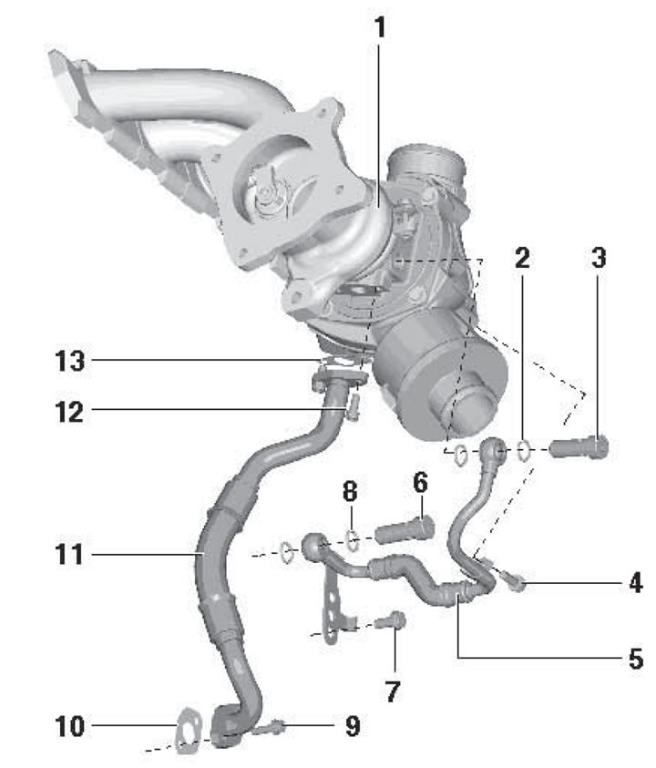
7.1b. Turbocharger Installation Details, Part 2 of 4 1. Turbocharger; 2.8. Sealing ring, subject to replacement; 3.6. Bolt, 35 Nm; 4.9. Bolt, 9 Nm; 5. Coolant supply pipe; 7. Bolt, 23 Nm; 10, 13. Gasket, subject to replacement; 11. Oil return pipe; 12. Bolt, 9 Nm
7.1c. Turbocharger Installation Details, Part 3 of 4 1. Gasket, subject to replacement; 2. Turbocharger mounting nut, 21 Nm, subject to replacement; 3. Bolt, 35 Nm; 4, 9, 13. Sealing ring, subject to replacement; 5. Coolant return hose and pipe; 6, 11. Bolt, 9 Nm; 7. Turbocharger; 8, 12. Bolt, 30 Nm; 10. Oil supply pipe; 14. Bolt, 23 Nm; 15. Bracket; 16. Support; 17, 18. Bolts, 30 Nm; 19. Nuts, 30 Nm, subject to replacement; 20. Fastening tape

7.1d. Turbocharger Installation Details, Part 4 of 4 1. Turbocharger; 2. Turbocharger vacuum module; 3. Bolt, 10 Nm; 4. Locking plate; 5. Nut, 9 Nm; 6. Knurled nut
2. Drain the coolant (see chapter 3).
3. Release the fasteners and remove the heat shield (see illustration).
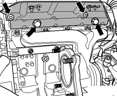
7.3. Fastening the heat shield
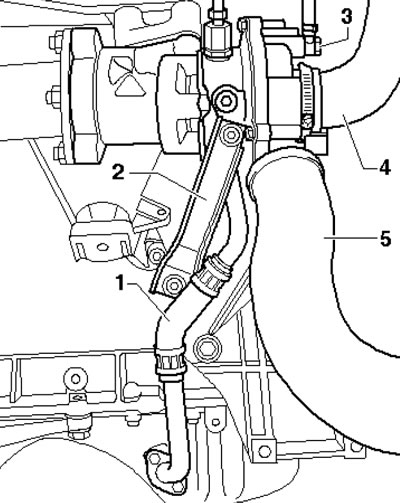
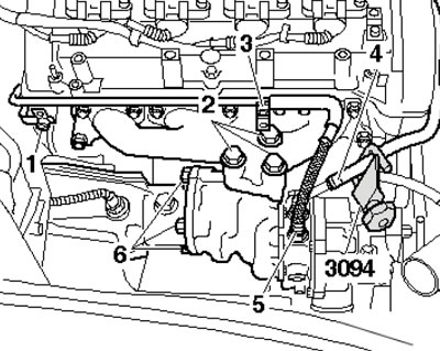
4. Remove the bolts (1 in the illustration) and disconnect the PCV line from the turbocharger and cylinder head cover (2). Disconnect the ACF line to the turbocharger from the cylinder head cover (3). Disconnect the oil feed pipe from the turbocharger (4).
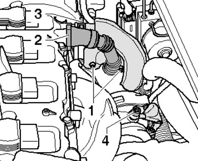
7.4 Turbocharger connections
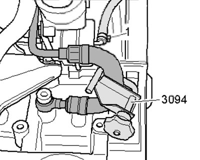
5. Remove the catalytic converter and disconnect the coolant supply line from the turbocharger (see illustration).
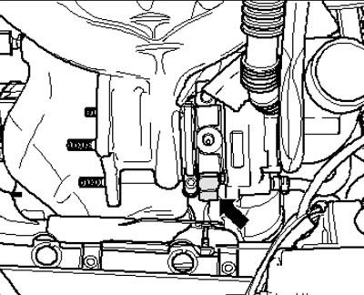
7.5. Coolant supply line to turbocharger
6. On models with independent/additional heating, unscrew the bolts (arrows in illustration 5.4 Chapter 2) its exhaust pipe from the soundproofing screen.
7. Release the fasteners (1 and 2 in Illustration 5.5 Chapter 2) and remove the front sound insulation. If there is rear sound insulation, release the clips (3) and remove it.
8. Disconnect the air supply hose (1 in illustration 17.7 Chapter 2), going to the turbocharger (bottom right) and the air supply hose (2) going to the intercooler.
9. Disconnect the connectors (1 and 2 in Illustration 17.32 Chapter 2) and move the wiring aside.
10. Unscrew the bolt (1 in illustration 25.18 Chapter 2) and disconnect the oil supply pipe to the turbocharger from the cylinder block. Unscrew the bolt (2) of the turbocharger support.
11. Unscrew the bolts and remove the oil supply pipe (see illustration 25.19 Chapter 2).
12. Disconnect the oil supply pipe from the turbocharger (see illustration 25.20 Chapter 2).
13. Loosen the turbocharger support mounting bolt by two turns (see illustration 25.21 Chapter 2).
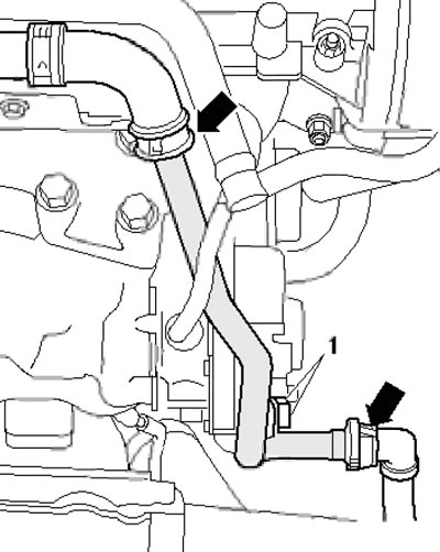
14. Disconnect the coolant pipe (see illustration 22.7 Chapter 2).
15. If available, unscrew the coolant pipe mounting bolts (1 in the illustration) on the cylinder head. Unscrew the upper nuts (arrows) securing the turbocharger and remove it with the exhaust manifold upwards.
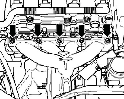
7.15. Turbocharger fastening
16. Installation is carried out in the reverse order of dismantling the components.
Engines 1.8 l
17. Turbocharger installation details are shown in the illustrations.
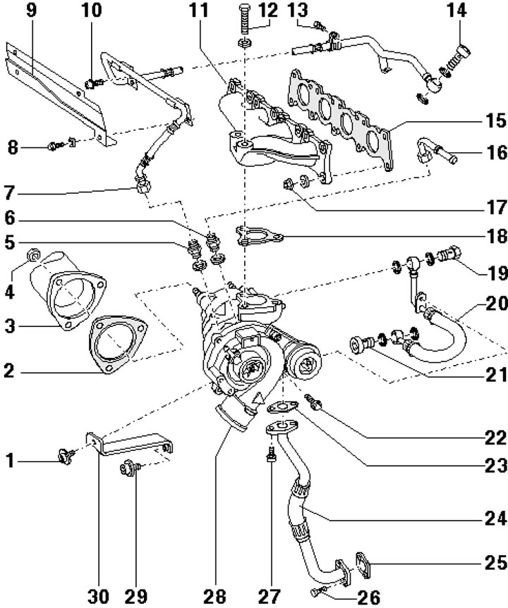
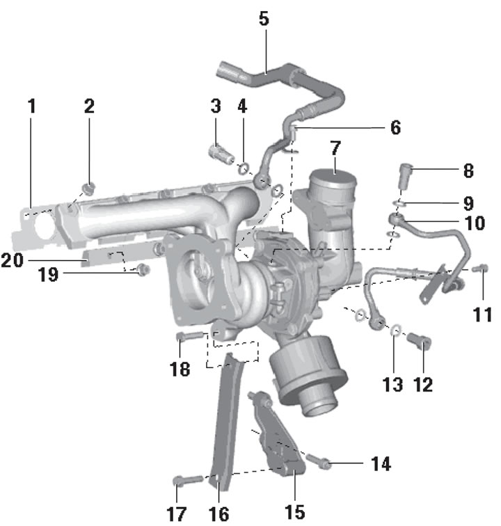
7.17a. Turbocharger Installation Details, Part 1 of 2 1. Bolt, 30 Nm, use original bolts; 2. Gasket, subject to replacement; 3. Catalytic converter; 4. Nut, 30 Nm, subject to replacement; 5/6. Threaded connection, 30/35 Nm; 7. Oil supply pipe, 23 Nm; 8. Bolt, 3.5 Nm; 9. Heat shield; 10. Bolt, 23 Nm; 11. Exhaust manifold; 12, 19. Bolt, 35 Nm, subject to replacement; 13. Bolt, 10 Nm; 14. Hollow bolt, 30 Nm; 15, 18. Gasket, subject to replacement; 16. Coolant return pipe, 30 Nm; 17. Nut, 30 Nm, subject to replacement; 20. Coolant supply pipe; 21. Hollow bolt, 35 Nm; 22. Bolt, 22 Nm; 23, 25. Gasket, subject to replacement; 24. Oil return pipe; 26, 27. Bolt, 10 Nm; 28. Turbocharger; 29. Bolt, 25 Nm; 30. Bracket
7.17b. Turbocharger Installation Details, Part 2 of 2 1. Vacuum hose to valve 2; 2. Mechanical air circulation valve; 3. Hose, to valve 2; 4. Air supply hose; 5. Hose to EVAP solenoid valve; 6. PCV tube; 7. Bolt, 10 Nm; 8, 10. Hose, to turbocharger; 9. PCV pressure control valve; 11. Hose to the vacuum module of the boost pressure control valve; 12. Solenoid valve for boost pressure regulation; 13. Corner; 14. Hose to turbocharger
18. On models with independent/additional heating, unscrew the bolts (arrows in illustration 5.4 Chapter 2) its exhaust pipe from the soundproofing screen.
19. Release the fasteners (1 and 2 in Illustration 5.5 Chapter 2) and remove the front sound insulation.
20. Remove the bracket fastener (2 in the illustration) turbocharger, disconnect the oil return pipe (1) from it and move it to the side. Loosen the fastening of the inlet hoses (4 and 5) on the turbocharger and unscrew the hollow bolt (3) of the pressure pipe.
7.20. Turbocharger connections
21. Disconnect the hose (1 in the illustration) vacuum block from the turbocharger and pinch the coolant supply hose at the bottom of the turbocharger.
7.21. Vacuum hose and coolant supply hose
22. Remove the upper engine soundproofing cover and air cleaner (see Section 3).
23. Remove the additional air tube (see illustration).
7.23. Additional air tube
24. Remove the heat shield (3 in illustration 34.5 Chapter 2) from the additional air tube (1) and the cylinder head cover.
Note: Please ignore point 2 in the illustration.
25. Release the bushing on the coolant return hose, remove the coolant return hose clamp, loosen the clamp (4 in the illustration) and disconnect the coolant return hose from the turbocharger (the nipple remains on the compressor). Remove the bolts (1 and 3) on the oil supply pipe (5) and disconnect it from the turbocharger. Remove the bolts (6) securing the catalytic converter to the turbocharger and the bolts (2) securing the turbocharger to the exhaust manifold.
7.25. Removing the turbocharger
26. Move the turbocharger to the side, unscrew the remaining bracket mounting bolts and the hollow bolt of the coolant supply pipe. Remove the turbocharger.
27. Installation is carried out in the reverse order of dismantling the components. Use new gaskets and self-locking nuts. After installation, let the engine run for about 1 minute at idle speed.
4-cylinder diesel engines
28. Turbocharger installation details are shown in the illustration.
7.28. Turbocharger installation details 1. Bolt, 15 Nm; 2. Oil return pipe to the cylinder block, 40 Nm; 3, 7. Gasket, subject to replacement; 4. Connection, 40 Nm; 5, 10. Sealing ring, subject to replacement; 6. Bolt, 20 Nm; 8. Catalytic converter with particulate filter; 9. Nut, 23 Nm, subject to replacement; 11. Connection, 30 Nm; 12. Bolt, 10 Nm; 13. To the oil filter holder; 14. Oil supply pipe, 22 Nm; 15. Vacuum hose from the boost pressure control solenoid valve; 16. Bolt, 25 Nm, subject to replacement; 17. Turbocharger; 18. Clamp, 3.5 Nm; 19. PCV hose; 20. Bolt, 8 Nm; 21. Air hose to the air cleaner housing; 22. Bracket; 23. Bolt, 23 Nm; 24. Sealing ring; 25. Intercooler feed hose
(This publication is borrowed from the resource: audimanual.ru)