
Repair Chevrolet Repair Toyota Repair Honda Repair AvtoVAZ Repair Mercedes-Benz Repair BMW Repair Opel
Home  |  Contacts  |  Sitemap  |    
English Русский
Български
Беларускі
Український
Српски
Hrvatski
Română
Polski
Slovenský
Magyar
AudiManual.ru


  • AUDI 80
  • AUDI 100
  • AUDI A3
  • AUDI A4
  • AUDI A6
  • AUDI A8
  • AUDI Q
  • OTHER
  • ARTICLES
B4 (1991-1996) B3 (1986-1991) B3 (1986-1991, petrol) B2 (1979-1986)

Turbocharger (Audi 80 B4)

  • Home
  • Audi 80
  • B4 (1991-1996)
  • Power unit
  • Diesel fuel system
  • Turbocharger
            0
The process of preparing and burning the air-fuel mixture in the combustion chambers of a diesel engine is quite long compared to a gasoline engine. For this reason, the maximum rotation speed of a diesel engine is limited. Otherwise, it will not operate economically. To increase the power of a diesel engine, a turbocharger can be used, which increases the amount of air entering the engine, providing a high filling factor.

A turbocharger consists of two turbine wheels mounted on a single shaft. Exhaust gases enter one wheel, driving it. Simultaneously with the rotation of the first wheel, the second one rotates, forcing atmospheric air into the combustion chambers (see illustration 16.0).
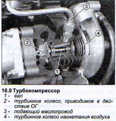
A turbocharger consists of two turbine wheels mounted on a single shaft. Exhaust gases enter one…


With such operation of the turbocharger, with an increase in its speed, excess air will be forced into the combustion chambers and the boost pressure will become such that the engine will not withstand it (see illustration 16.0a).
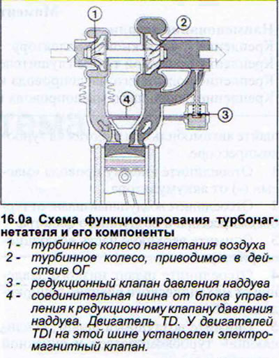
With such operation of the turbocharger, with an increase in its speed, excess air will be forced…


To avoid this situation, TD engines are equipped with a boost pressure reducing valve. This valve opens, allowing only part of the exhaust gas to reach the compressor turbine wheel, thus maintaining the boost pressure within 0.83 bar.


The TDI engine is also equipped with a regulator. However, in this case, the regulator functions differently than in TD engines and limits the boost air pressure. This is done using a solenoid valve located at the rear of the engine compartment on the right side. This valve opens the pressure reducing valve via a rod from the diaphragm valve, reducing the boost air pressure. The solenoid valve is controlled by the fuel system control unit according to information from the intake manifold pressure sensor. The intake manifold pressure sensor is connected to the intercooler via a thin hose (charge air cooler). Thus, the boost pressure regulator is able to compensate for the decrease in air density in areas with high altitudes.

Boost Air Pressure Regulator Solenoid Valve - Check

1. Make sure that the hoses attached to the valve are not mixed up.

2. Measure the internal resistance of the valve. To do this, disconnect the valve plug.

3. Connect a sensitive ohmmeter to both contacts of the plug. It should show 24-28 ohms. Otherwise, the boost pressure limiting solenoid valve is faulty and must be replaced.

4. Check the supply of power to the solenoid valve. To do this, connect the voltmeter to terminal 2 of the connecting plug and to the "ground" (see illustration).
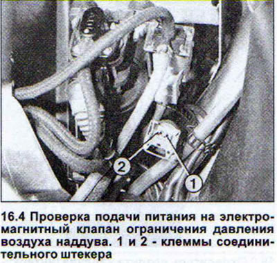
4. Check the supply of power to the solenoid valve. To do this, connect the voltmeter to terminal 2…


5. Turn on the ignition. The voltmeter should show the battery voltage. Otherwise, the power supply wire is broken.


The procedure for checking the intake manifold pressure sensor is indicated in the relevant chapter.

Boost Air Pressure Limiting Diaphragm Valve - Check


6. Warm up the engine to operating temperature.

7. Check the plug of the boost pressure limiting solenoid valve.

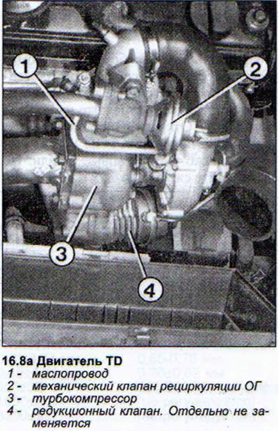
8. Start the engine and increase its speed to maximum. The pressure reducing valve drive rod from the diaphragm valve should shift (see illustration).
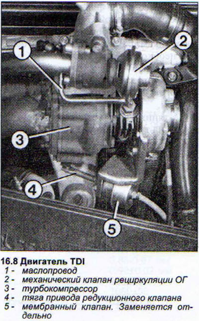
8. Start the engine and increase its speed to maximum. The pressure reducing valve drive rod from…


8. Start the engine and increase its speed to maximum. The pressure reducing valve drive rod from…


Note: Shutting down the engine immediately after a long drive at full load is harmful to the turbocharger. This treatment of the turbocharger can lead to "coking" of the supercharger. The shaft bearing next to the turbine wheel heats up to such an extent due to the sudden accumulation of hot air that all the grease in the bearing burns and sticks to the rubbing surfaces. If the engine is constantly shut down in this way, the turbocharger will not last long. Therefore, after a long drive in the "Full Load" mode, it is recommended not to shut off the engine, but to let it idle for a while.

Note: Shutting down the engine immediately after a long drive at full load is harmful to the…
The article was checked by auto expert Timur Bazhenov
This article is available at russian, bulgarian, belarusian, ukrainian, serbian, croatian, romanian, polish, slovak, hungarian

Share information:
Previous articles
Audi 80 B4: Diesel fuel system
Next articles

TDI Engine Preheating System — Check
TDI engine preheating system
TD Engine Preheating System — Check
TD Engine Preheating System
Turbocharger — removal and installation
Charge air cooler


Similar articles on other Audi car models:
Operating principle of turbocharger of MPI and MPFI injection… Audi 100 C4 (1990-1994)
Engine Management System 1.8L without Turbocharger Audi A3 Type 8L (1996-2003)
Turbocharger Audi A4 B5 (1994-2001, petrol)
Device, removal and installation of turbocharger Audi A6 C4 (1994-1997)
Device, removal and installation of turbocharger Audi A8 D2 (1994-2002)
Turbocharger — removal and installation Audi Q5 Type 8R (2008-2017)
Turbocharger — design description Audi A2 (1999-2005)
Link to this page in different formats


Visitor comments

No comments yet


How much will 40 + 29 =


80(B4, 1991-1996) 
  • General information
  • User manual
  • Maintenance
  • Troubleshooting
  • Power unit
  • Engine
  • Cooling system
  • Heating and ventilation
  • Petrol injection
  • Diesel fuel system
  • Fuel system
  • Exhaust systems
  • Ignition system
  • Transmission
  • Clutch
  • Car gearbox
  • Chassis
  • Brake system
  • Suspension and steering wheel
  • Body
  • Body and trim
  • Electrical equipment
  • Electrical system
  • Electrical circuits
 
80(B3, 1986-1991) 
  • General information
  • Repair characteristics
  • Maintenance
  • Power unit
  • Gasoline engine
  • Diesel engine
  • Engine lubrication system
  • Fuel system (gasoline)
  • Injection system (gasoline)
  • Fuel system (diesel)
  • Ignition system
  • Cooling system
  • Heater
  • Exhaust system
  • Transmission
  • Clutch and gearbox
  • Chassis
  • Steering
  • Brake system
  • Car suspension
  • Body
  • Body elements
  • Electrical equipment
  • Power devices
  • Lighting and appliances
  • Electrical circuits
 
80(B3, 1986-1991, petrol) 
  • General information
  • User manual
  • Maintenance
  • Power unit
  • Engine 4-cylinder
  • Engine 5-cylinder
  • Cooling system
  • Fuel and exhaust systems
  • Ignition system
  • Transmission
  • Clutch
  • Mechanical transmission
  • Automatic transmission
  • Drive shafts
  • Chassis
  • Brake system
  • Suspension
  • Steering
  • Body
  • Exterior
  • Interior
  • Electrical equipment
  • Equipment and devices
  • Electrical circuits
 
80(B2, 1979-1986) 
  • General information
  • User manual
  • Power unit
  • Engine FZ
  • Engine EP, YP, YZ, DT, DS, DZ
  • Transmission
  • Clutch
  • 4 speed gearbox
  • 5 speed gearbox
  • Front wheel drive
  • Chassis
  • Front suspension
  • Rear suspension
  • Steering
  • Brake system
  • Electrical equipment
  • Equipment and devices
  • Electrical circuits
 
AudiManual.ru © 2017-2026 · Mobile version · Feedback · Sitemap: EN BG BY UA RS HR RO PL SK HU · Site search · News and articles
80 B2 · 80 B3 petrol · 80 B3 · 80 B4 · 100 C3 diesel · 100 C3 petrol · 100 C3 · 100 C4 petrol · 100 C4 · A3 Type 8L · A4 B5 petrol · A4 B5 · A4 B6 petrol · A4 B6 · A4 B7 · A4 B8 · A6 C4 · A6 C5 · A6 C5 Allroad · A8 D2 · Q5 Type 8R · Q7 Typ 4L · Audi A2 ·
This site uses cookies 🍪. Click the button to accept this fact.