
Table of contents: Installation position of the… ↓ Turbocharger. Tightening sequence ↓ Removal the turbocharger ↓ Install ↓ Removal the charge air cooler ↓ Install ↓ Removal the boost pressure sensor… ↓ Install ↓
Note. All hose connections must be secured with standard clamps corresponding to the model year. Hoses and hose nipples of the air-supply system must be cleaned of oil and grease before installation. Only in the case of nipple connections the sealing ring and sealing surface must be lightly moistened with oil. The air-supply system must be airtight. Self-locking nuts must be replaced. For installation of spring band clamps it is recommended to use special pliers "VAS 6362" or special pliers "V.A.G 1921". Fill the turbocharger with oil through the connecting pipe for the oil supply line. After installing the turbocharger, let the engine run at idle speed (do not increase the speed) for 1 minute to ensure oil is supplied to the turbocharger. Maintain cleanliness standards.
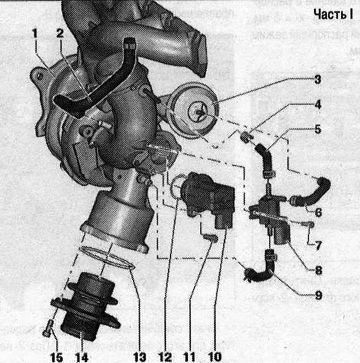
Part I 1. Turbocharger. May only be replaced as a set with the exhaust manifold and vacuum block; 2. Hose; 3. Turbocharger vacuum block. Can only be replaced with a turbocharger; 4. Hose clamp; 5/6. Hose; 7. Bolt. 3 Nm; 8. Electromagnetic boost pressure limiting valve "N75"; 9. Hose; 10. Turbocharger air bypass valve "N₂49". Observe installation position; 11. Bolt. 7 Nm; 12/13. Sealing ring. Replace; 14. Support; 15. Bolt. 9 Nm
Installation position of the turbocharger air bypass valve "N₂49"
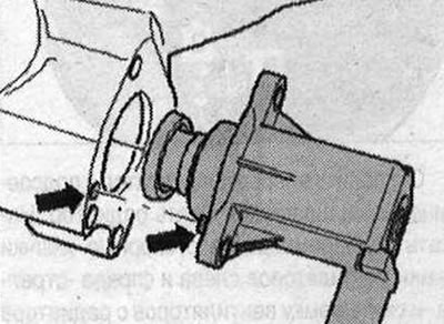
Take into account the installation position of the "arrow"
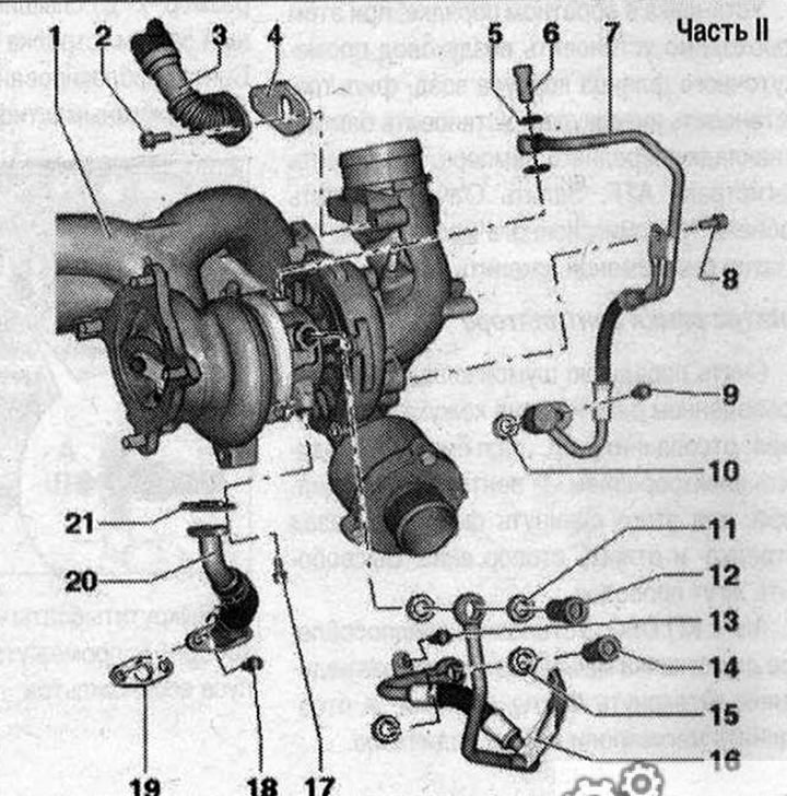
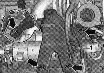
Part II 1. Turbocharger. May only be replaced as a set with the exhaust manifold and vacuum block; 2/8/9/13/17/18. Bolt. 9 Nm; 3. Engine crankcase ventilation pipe; 4. Gasket. Replace; 5. Lip seal. Replace; 6. Bolt 30 Nm; 7. Oil supply line; 10. Sealing ring. Replace; 11. Lip seal. Replace; 12/14. Bolt. 35 Nm; 15. Lip seal. Replace; 16. Coolant pressure line; 19/21. Gasket. Replace; 20. Return oil line
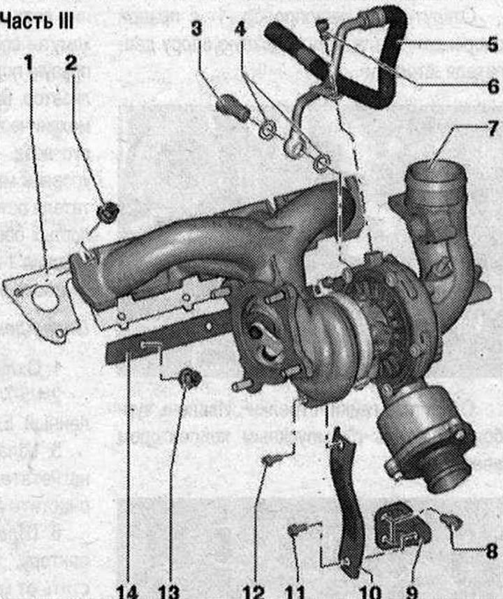
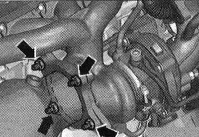
Part III 1. Gasket. Replace; 2. Nut. Replace. Lubricate the exhaust manifold mounting pins with heat-resistant paste; 3. Bolt 35 Nm; 4. Lip seal. Replace; 5. Return coolant line; 6. Bolt. 9 Nm; 7. Turbocharger. May only be replaced as a set with the exhaust manifold and vacuum block; 8/11. Bolt. 30 Nm; 9. Bracket; 10. Support; 12. Bolt. 30 Nm. Lubricate the bolt with heat-resistant paste; 13. Nut. Do not loosen to remove turbocharger. Replace. 30 Nm. Lubricate exhaust manifold mounting pins with heat-resistant paste; 14. Clamping bar
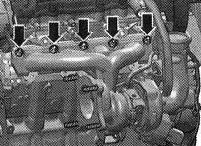
Turbocharger. Tightening sequence
Tighten bolts "1...5" in 4 stages:
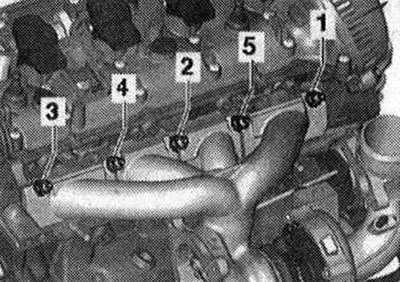
- 1. Tighten the bolts to 5 Nm.
- 2. Tighten the bolts to 12 Nm.
- 3. Tighten the bolts to 16 Nm.
- 4. Tighten the bolts to 25 Nm.
Removal the turbocharger
Remove the engine casing "arrows". Drain the coolant. Remove the air duct "arrow".
Disconnect the plug connector "2-ras" of the air flow meter "G70". Remove the air duct hose from the air flow meter "G70" by loosening the hose clamp "3". Remove the air filter housing "1" upwards.
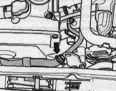
Disconnect the cooling system hose "arrow".
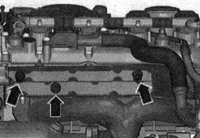
For better understanding, the installation position is shown with the engine removed. Remove the heat shield "arrows".
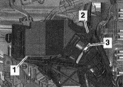
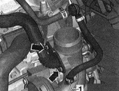
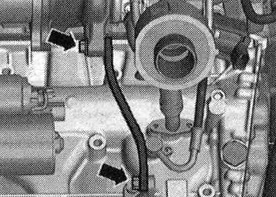
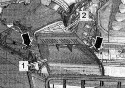
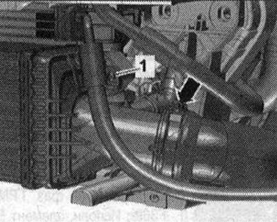
Disconnect the crankcase ventilation system of the "arrow" engine from the turbocharger. Disconnect hose "1" from the turbocharger.
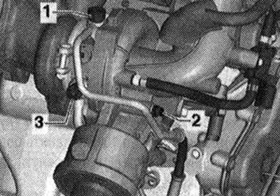
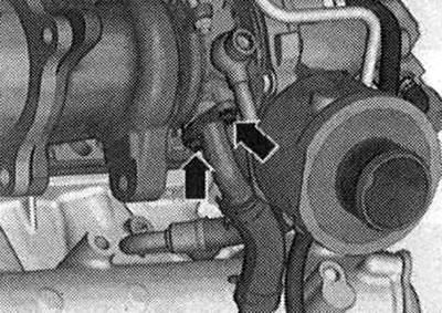
Unscrew bolts "1 and 2" and set aside the oil supply line. Unscrew bolt "3" and set aside the coolant line.
Disconnect the hose clamp "arrow", remove the air duct hose and set it aside.
Disconnect connectors "1 and 2" and release the electrical wiring.
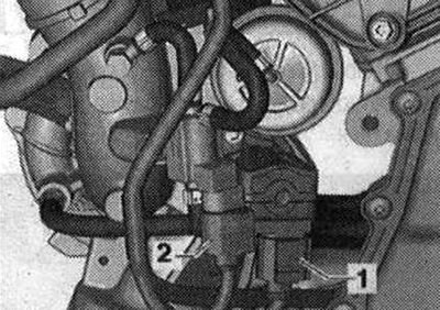
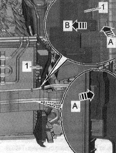
Unscrew the "arrow" bolts and remove the turbocharger support.
Unscrew the bolts "arrow" of the oil drain pipe.

Risk of damage to the front muffler release components. Do not tilt the release components in the front muffler more than 10. Loosen the bolted connections "arrows" and move the clamping sleeve back.
Lower the front muffler a little and tie it to the crossbar "arrow".
Unscrew the "arrow" nuts and press the catalytic converter back. Remove the right engine mount.
Unscrew the electrical wire "1" from the right engine support. Remove the right engine support "arrows".
Unscrew the nuts "arrows". Remove the turbocharger with the exhaust manifold upwards.
Install
Installation is carried out in the reverse order, taking into account the tightening torques. Replace the gasket sealing rings, O-rings and self-locking nuts. Fill the turbocharger with oil through the oil supply line nipple. The hoses and hose nipples of the air boost system must be cleaned of oil and grease before installation. Use clamps of the appropriate series to secure all hose connections. Install the right engine mount. Install the catalytic converter. Align the exhaust system without mechanical stress. Install the air filter housing. Fill with coolant. Check the oil level. After installing the turbocharger, let the engine run at idle speed (do not increase the speed) for 1 minute to ensure oil is supplied to the turbocharger.
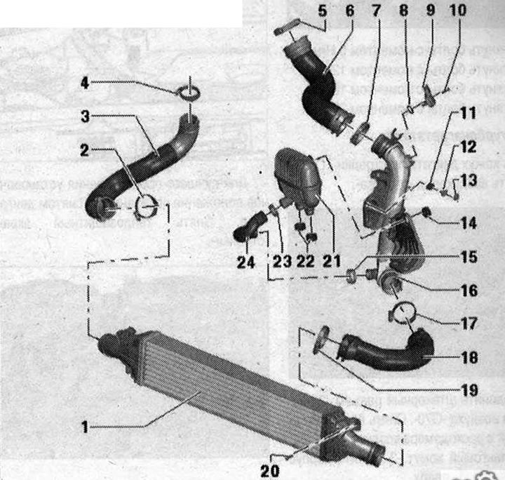
Charge air cooling 1. Charge air cooler; 2/4/5/7/15/17/19/23. Hose clamp. Reinforced. 5.5 Nm; 3. Air duct hose going to turbocharger. Before installation it should be cleaned from oil and grease; 6. Air duct hose to intake manifold. Before installation, clean from oil and grease; 8. Sealing ring. Replace; 9. Boost pressure sensor "G31"; 10. Bolt. 5 Nm; 11. Rubber tip; 12. Bushing; 13. Nut. 9 Nm; 14. Rubber tip; 16. Air guide tube 18. Air duct hose from intercooler. Before installation, clean from oil and grease; 20. Bolt. 7 Nm; 21. Resonator; 22. Rubber tip; 24. Air duct hose to resonator. Before installation, clean from oil and grease
Removal the charge air cooler
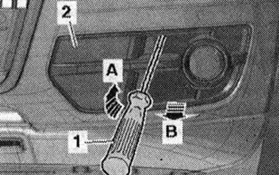
Unlock the lock "arrow A" with a screwdriver "1". Disconnect the air intake grille "2" from the bumper cover "arrow B". Repeat the entire process of performing the work on the other side of the car.
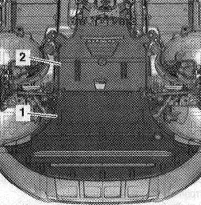
Remove front noise insulation "1".
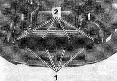
Unscrew bolts "1" and "2", remove the noise insulation screen of the bumper trim in the rear direction.
To remove the "arrow" spacer clamp, carefully press the clamping pin "1" by the dimension "x" until an audible click is heard into the "arrow A" spacer clamp. Dimension "x" = 5 mm.
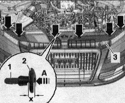
Remove the unlocked spacer clamp "2" with the clamping pin. Lift the cover "3" of the radiator frame and hang it on the radiator grille. Unscrew the bolts "arrows". Remove the air duct "1" from the intermediate flange "2" of the air filter housing.
Unlock the fastening brackets "arrows A" and move the air duct "1" to the left and right towards the center of the car "arrow B".
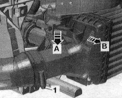
Remove the air duct hose from the intercooler by loosening the hose clamp "arrow". Unscrew bolt "1".
Remove the air duct hose from the intercooler by loosening the hose clamp "1". Press the retainer down "arrow A" and slightly tilt the upper part of the intercooler "in the direction of arrow B".
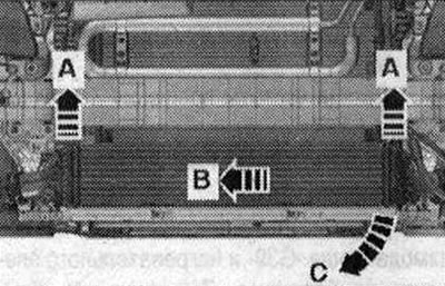
For better understanding, the installation position is shown with the power steering pump removed. Remove the intercooler from the radiator in the upward direction "arrow A" and press "in the direction of arrow B". Pull the bumper cover forward and remove the intercooler from the left side in the downward direction "arrow C".
Install
Installation is carried out in the reverse order, taking into account the tightening torque. The hoses and hose fittings of the air boost system must be cleaned of oil and grease before installation. Use clamps of the appropriate series to secure all hose connections. To ensure reliable fastening of the air boost hoses to the fittings, treat the threaded connections of the already used clamps with a rust remover.
Removal the boost pressure sensor "G31"
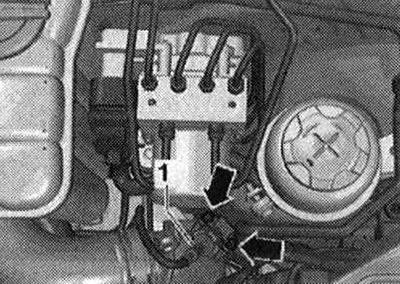
Disconnect plug connector "1" of boost pressure sensor "G31". Unscrew bolts "arrows" and pull boost pressure sensor "G31" out of air guide pipe.
Install
Install in reverse order, taking into account the tightening torque. Replace the sealing ring.
(The text is based on materials from the website: «audimanual.ru»)