
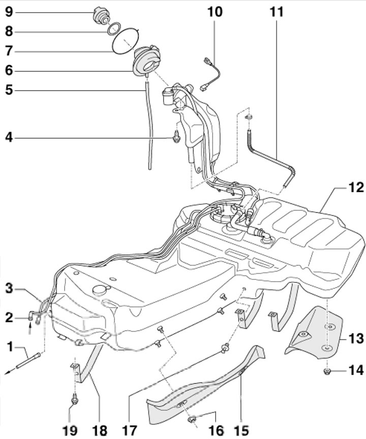
11.1a. Fuel tank installation details for MPI and 2.0 FSI petrol engines of FWD models 1. Fuel supply pipe from the fuel filter to the engine; 2. Return fuel pipe from the engine; 3. EVAP tube to carbon canister; 4. Bolt, 23 Nm; 5. Overflow hose; 6. Rubber hatch; 7. Retaining ring; 8. Compaction; 9. Fuel tank cap; 10. Connection to ground; 11. Ventilation tube; 12. Fuel tank; 13, 15. Heat shield; 14, 16. Nut, 2 Nm; 17. Retainer; 18. Tank mounting clamp 19 Bolt, 23 Nm
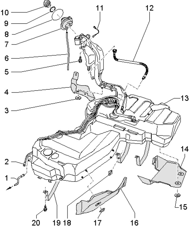
11.1b. Fuel tank installation details for 4-cylinder TFSI petrol engines and 6-cylinder FSI petrol engines (fWD models) 1. Fuel supply pipe from the fuel filter to the engine; 2. EVAP tube to carbon canister; 3. Nut, 2 Nm; 4. Thermal protection screen of the filler neck; 5. Bolt, 23 Nm; 6. Overflow hose; 7. Rubber hatch; 8. Retaining ring; 9. Compaction; 10. Fuel tank cap; 11. Connection to ground; 12. Ventilation tube; 13. Fuel tank; 14, 16. Heat shield; 15, 17. Nut, 2 Nm; 18. Retainer; 19. Tank mounting clamp; 20. Bolt, 23 Nm
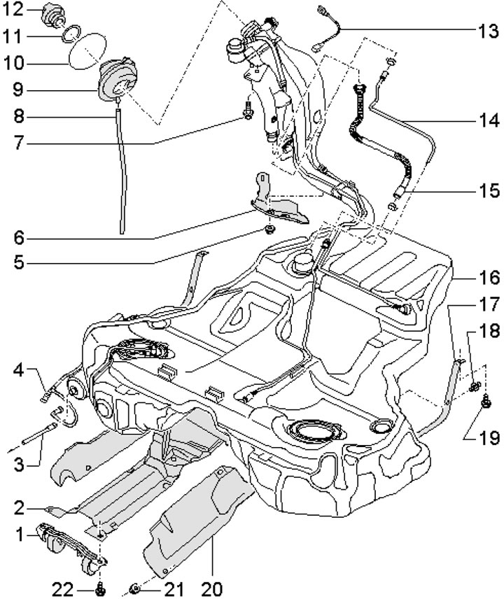
11.1c. Fuel tank installation details for petrol AWD models 1. Exhaust pipe bracket; 2. Support bracket; 3. Fuel supply pipe from the fuel filter to the engine; 4. EVAP tube to carbon canister; 5. Nut, 2 Nm; 6. Thermal protection screen of the filler neck; 7. Bolt, 23 Nm; 8. Overflow hose; 9. Rubber hatch; 10. Retaining ring; 11. Compaction; 12. Fuel tank cap; 13. Connection to ground; 14, 15. Ventilation tube; 16. Fuel tank; 17. Tank mounting clamp; 18. Retainer; 19, 22. Bolt, 23 Nm; 20. Heat shield; 21. Nut, 2 Nm
2. Disconnect the negative cable from the battery (see Chapter 5).
3. Open the fuel tank cap and close it again to equalize the pressure in the tank with the atmospheric pressure.
4. On Sedan models, remove the trim panel in the luggage compartment and, if necessary, fold the right seatback forward.
5. On Station Wagon models, remove the left rear seatback, left cargo area trim panel and mudguard.
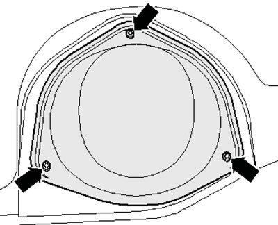
6. Remove the bolts securing the service hole cover (see illustration) and take it off.
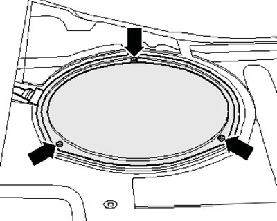
11.6. Fastening the service port cover
7. Disconnect the ventilation hoses (1 and 2 in the illustration).
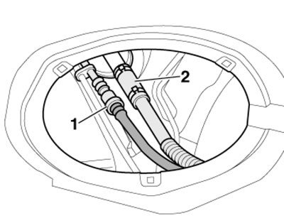
11.7. Pipe connections under the service port
8. Remove the rear seat (see Chapter 11) and remove the covers of both service holes (see illustration).
11.8. Fastening the service hole cover under the rear seat
9. Disconnect the connectors on the right and left sides (see illustrations).
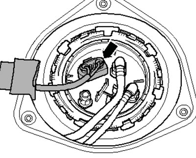
11.9a. Connector under the right service cover
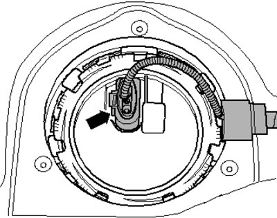
11.9b. Connector under the left service cover
10. Detach the loop (1 in the illustration) from the filler cap, clean the area around the neck (without removing the lid), pry up the retaining ring (arrow) and press the rubber neck inward.
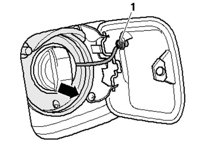
11.10. Removing the rubber neck
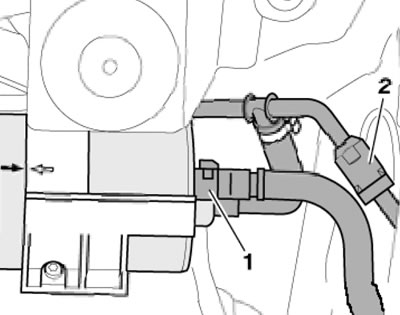
11. Remove the rear right wheel and the right rear wheel arch liner. Disconnect the ventilation pipes (2 and 3 in the illustration) from the filler neck and unscrew the bolt (1) securing the filler neck.
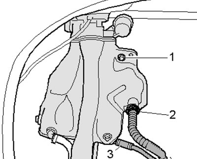
11.11. Removing the filler neck
12. Remove the rear section of the exhaust pipe (see Part B), propeller shaft and rear drive shafts (see Chapter 8).
13. Remove the heat shields (1 and 2 in the illustration).
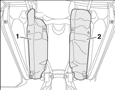
11.13. Thermal protection screens
14. Remove the parking brake cables from the holders shown in the illustration.
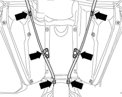
11.14. Parking brake cable holders
15. Disconnect the fuel and vent lines (see illustrations) from the front right side of the fuel tank. On models with an independent heater, additionally disconnect its fuel line.
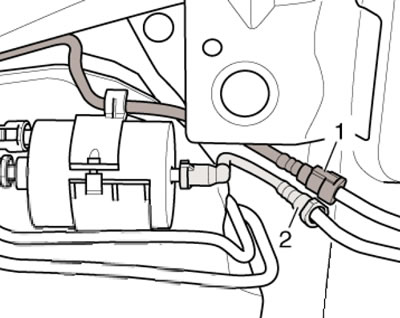
11.15a. Fuel and ventilation lines
11.15b Fuel lines of the 1.8T engine
16. Support the fuel tank with a transmission jack and remove the bolts (1-10 in the illustration) and lower the tank on the jack, guiding it with your hand.
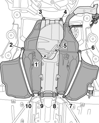
11.16. Removing the fuel tank
17. Installation is carried out in the reverse order of dismantling the components. Make sure that neither end of the ground connection is oxidized. Connector (4 in the illustration) must be located on the metal ring (3), and the contact bracket (2) must be connected to the tank (5) and secured with a spacer sleeve (1), if present.
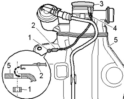
11.17. Wiring diagram
(The article was copied from the website: «Audimanual.ru»)