
Table of contents: Diesel engines 1.9 and 2.0 SOHC ↓ Diesel engines 2.0 DOHC ↓
Diesel engines 1.9 and 2.0 SOHC
1. Remove the cylinder head cover (see Chapter 2).
2. Turn the crankshaft so that both cams of the corresponding unit injector are facing upward.
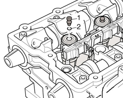
3. Loosen the locknuts of the adjusting bolts (1 in the illustration) on all unit injectors and unscrew the adjusting bolts so that each rocker arm contacts the push spring of the corresponding unit injector. Remove the rocker arm shaft by unscrewing the bolts (2), starting with the outer ones. Unscrew the bolt (3) and remove the retaining block.
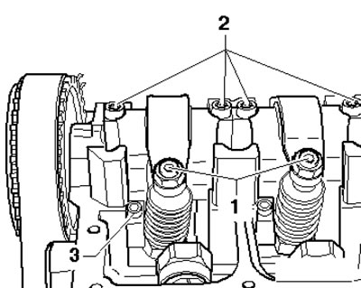
9.3. Removing the retaining block
4. Using a screwdriver, press the connector away from the pump-injector (see illustration). Gently press the opposite side of the connector with your finger to prevent it from becoming crooked.
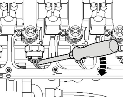
9.4. Electrical wiring connector
5. Insert the T10055 puller into the groove on the side of the unit injector in place of the retaining block and pull the unit injectors out of the cylinder head by pulling and slightly rocking the device (see illustration).
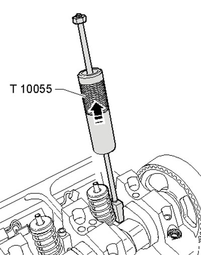
9.5. Removing the pump-injector
6. New unit injector bolts will be required for installation. When replacing a unit injector, the corresponding adjusting bolt on the rocker arm must also be replaced. When installing old unit injectors, the sealing rings and insulating gasket must be replaced.
7. Make sure that the sealing rings are not twisted, lubricate them and the guide of the unit injector in the cylinder head. Very carefully insert the unit injector into the seat of the cylinder head and press it until it stops. Insert the retaining block.
8. If the unit injector is not installed at a right angle to the retaining block, the mounting bolt may come loose, which will result in damage to the unit injector or cylinder head. To align the unit injector, screw a new mounting bolt into the retaining block so that the unit injector can be slightly rotated, then align the unit injector at an angle to the camshaft bearing elevations and check the distance (and in the illustration) from the outer edge of the cylinder head to the rounded edge of the pump-injector. For pump-injectors with a nut with a cylindrical sleeve, this dimension should be 332.2, 244.2, 152.8 and 64.8 for cylinders No.1-4, respectively, with a tolerance of ±0.8 mm. For pump-injectors with a nut with a beveled sleeve, this dimension should exceed the specified ones by 0.8 mm with the same tolerance.
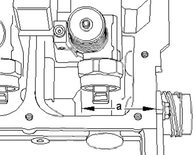
9.8. Checking the position of the pump-injector (using the example of a pump-injector with a nut with a cylindrical sleeve)
9. If necessary, adjust the position of the pump-injector, tighten the mounting bolt with a force of 12 Nm, and tighten it by 3/4 of a turn. Tighten the inner (2 in illustration 44.9 Chapter 2), and then the outer (1) bolts with a torque of 20 Nm, and then tighten them by 1/4 turn.
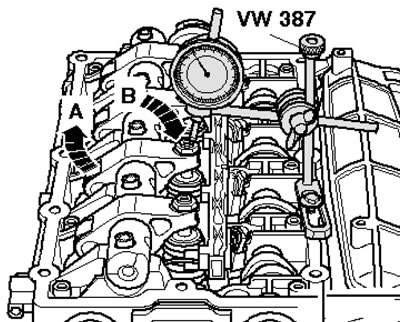
10. Fit a plunger type dial gauge to the adjusting bolt as shown in the illustration and rotate the crankshaft until the rocker roller is at the end of the cam. In the illustration, the roller side (A) is shown at the highest point and the dial gauge (B) is shown at the lowest point. Remove the gauge, screw the adjusting bolt into the rocker arm until significant resistance is felt and back it out half a turn. While holding the adjusting bolt in this position, tighten the lock nut to 30 Nm.
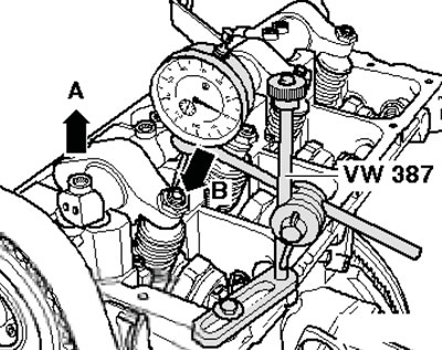
9.10. Checking the stroke of the pump-injector
11. Further installation is carried out in the reverse order of dismantling the components.
Diesel engines 2.0 DOHC
12. The details of the pump-injector installation are shown in the illustration.
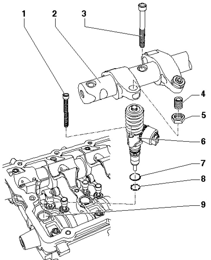
9.12. Unit-injector installation details 1. Bolt, 3 Nm, then tighten to an angle of 90°, then tighten to an angle of 180°, subject to replacement; 2. Rocker arm axle with rocker arms; 3. Bolt, 20 Nm, then tighten to an angle of 90°, subject to replacement; 4. Adjusting bolt, subject to replacement; 5. Lock nut; 6. Pump injector; 7, 8. Sealing ring, subject to replacement; 9. Cylinder head
13. Remove the cylinder head cover (see Chapter 2).
14. Turn the crankshaft so that both cams of the corresponding unit injector are facing upwards.
15. Loosen the lock nuts (2 in illustration 47.13 Chapter 2) adjusting bolts (1) on all unit injectors and unscrew the adjusting bolts so that each rocker arm touches the push spring of the corresponding unit injector.
16. Remove the bolts (1, 3 and 5 in Illustration 47.14 Chapter 2), and then the bolts (2 and 4). Remove the rocker arm shaft without removing the bolts from it, so as not to mix them up later.
17. Disconnect the glow plug and pump injector wiring connectors, unscrew the bolts on the retaining clips and remove the wiring harness to the side.
18. Unscrew the bolts using a suitable wrench (see illustration).
9.18. Pump-injector mounting bolts
19. Pull out the ball studs (1 in the illustration) from the removable pump-injector
9.19. Pump injector stud
20. Insert the T10163 puller into the holes of the pump-injector bolts (see illustration), lightly screw the spindle (A) onto the pump-injector and tighten the lock nut (B) by hand. Using a T10133/3 sliding hammer, knock the pump-injector out of its seat.
Note: Do not confuse the pump injectors.
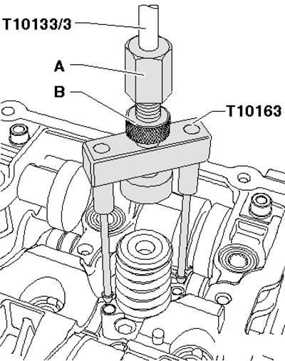
9.20. Removing the pump-injector
21. New unit injector bolts will be required for installation. When replacing a unit injector, the corresponding adjusting bolt on the rocker arm must also be replaced. When installing old unit injectors, the sealing rings and insulating gasket must be replaced. The sealing rings with white markings are installed in the lower groove of the unit injector.
22. Very carefully insert the unit injector into the cylinder head seat. Mount the 2036 tool and the 2036/1 mounting plates on the cylinder head retaining frame (see illustration).
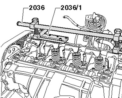
9.22. Device 2036
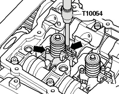
23. Screw in the new mounting bolts by hand until they are snug (see illustration).
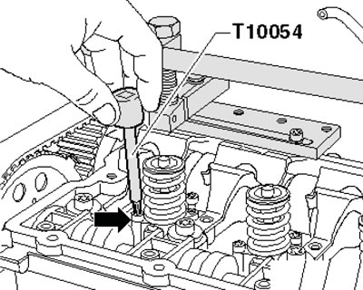
9.23. Bolt T10054
24. Install the VW541/1A lever using the VW541/5 compression tool and carefully press the unit injector into the cylinder head (see illustration). Screw in the pump-injector mounting bolts by hand until they fit, and then with the required force.
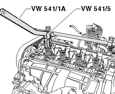
9.24. Installing the pump-injector
25. Further installation is carried out in the reverse order. After tightening the rocker shaft mounting bolts, install a plunger-type dial gauge on the adjusting bolt and turn the crankshaft so that the rocker roller is at the end of the camshaft cam. Roller side (And in the illustration) is at the highest point, and the side of the meter (B) is at the lowest point.
9.25. Adjusting the pump-injector
26. Remove the gauge, screw the adjusting bolt into the rocker arm until you feel significant resistance, and unscrew it half a turn. Holding the adjusting bolt in this position, tighten the lock nut with a force of 30 Nm.
This article was copied from the website: AUDImanual.ru