
Table of contents: Cylinder head cover ↓ Cylinder head ↓
1. The details of the cylinder head and its cover installation are shown in the illustration.
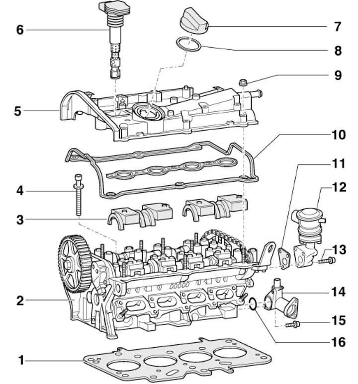
34.1. Cylinder head and cover installation details 1. Cylinder head gasket; 2. Cylinder head; 3. Camshaft bearing caps; 4. Engine oil distributors; 5. Cylinder head cover; 6. Ignition coil; 7. Oil filler cap; 8. Cover gasket 7; 9. Cylinder head cover fastening nuts, 9 Nm; 10. Cover gasket 5; 11. Valve gasket 12, subject to replacement; 12. SAI combination valve; 13. Valve mounting bolts 12, 10 Nm; 14. Coolant flange with ECT sensor; 15. Flange mounting bolts 14, 10 Nm; 16. Flange sealing ring 14, subject to replacement
Cylinder head cover
2. Release the fasteners (arrows in illustration 29.9) and remove the top engine cover.
3. If there is a casing (1 in illustration 5.11) on the right side of the engine compartment, remove this cover.
4. Disconnect the EVAP valve solenoid connector (1 in illustration 5.12) and remove the solenoid valve. Unscrew the screws (arrows) and remove the air duct (2).
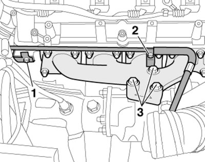
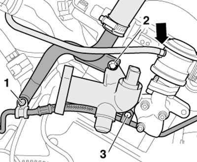
5. Remove the PCV tube (2 in the illustration) and the PCV hose from the cylinder head cover. Disconnect the SAI combination valve tube (1) from the cylinder head cover and heat shield (3). Bend the SAI tube slightly to the side.
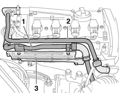
34.5. Tubes and hoses on the cylinder head cover
6. Disconnect the ground wire (2 in the illustration), disconnect the connectors (3) and set the wiring aside. Pull out the ignition coils (1).
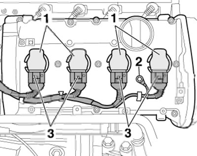
34.6. Removing the ignition coils
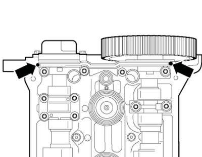
7. Release the two clamps of the upper timing belt cover, loosen the nuts (see illustration) and remove the cylinder head cover.
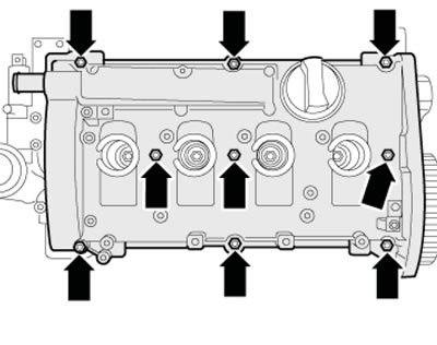
34.7. Cylinder head cover fasteners
8. Prepare new sealing elements. Replace the cylinder head cover gasket if the old gasket is damaged.
9. Apply a small amount of sealant to the indicated points on the cylinder head at the front and also at the rear (by analogy).
34.9. Places of sealant application
10. Install the cylinder head cover and tighten its inner nuts, then tighten the outer nuts in a diagonal sequence.
11. Further installation is carried out in the reverse order of dismantling the components.
Cylinder head
12. Disconnect the negative cable from the battery.
13. Drain the coolant from the cooling system.
14. Install the radiator frame in the service position (see Section 30).
15. Remove the upper coolant pipe (see Chapter 3) and the intake manifold (see Chapter 4).
16. Remove the timing belt from the camshaft sprocket (see Section 32).
17. Disconnect the connector (3 in illustration 29.21) EVAP valve solenoid and air flow meter connector (5), disconnect the hoses (1, 4, 6 and 7), remove the retainer (2) and detach the air cleaner housing.
18. Remove the PCV tube (2 in illustration 34.5) and the PCV hose from the cylinder head cover. Disconnect the SAI combination valve tube (1) from the cylinder head cover and heat shield (3). Tilt the SAI tube slightly to the side and remove the heat shield.
19. Remove the bolts (1 and 2 in the illustration) supply oil line, as well as the bolts (3) of the turbocharger.
34.19. Fastening the turbocharger and its supply oil line
20. Disconnect the intake camshaft adjustment valve connector (see illustration).
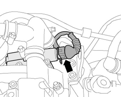
34.20. Camshaft control valve connector
21. Disconnect the ECT sensor connector (see illustration).
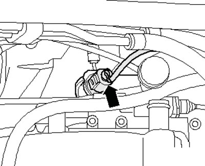
34.21. ECT sensor connector
22. Disconnect the vacuum hose (arrow on the illustration) from the SAI combination valve, remove the coolant flange (bolts 2 and 3) and unscrew the bolt (1) securing the bracket for the oil supply line. Separate all electrical wiring from the cylinder head and set it aside. Disconnect the air conditioning radiator hose at the rear of the cylinder head (is fixed with a clamp on the flange).
34.22. Cylinder head end connections
23. Disconnect the ground wire (2 in illustration 34.6), disconnect the connectors (3) and set the wiring aside. Pull out the ignition coils (1).
24. Release the two fasteners of the upper timing belt cover, loosen the nuts (see illustration 34.7) and remove the cylinder head cover.
25. Remove both oil distributors (4 in illustration 34.1).
26. Remove the cylinder head mounting bolts in the following sequence: (1-10 in the illustration) and remove it with the help of an assistant. The installation procedure is described below.
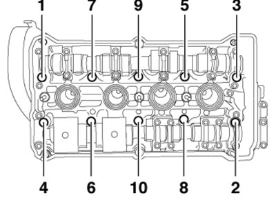
34.26. Sequence of unscrewing the cylinder head mounting bolts
27. Inspect the cylinder head. If there are small cracks on it, (width up to 0.3 mm) between the valve seats or between the valve seat ring and the spark plug socket thread (no further than the first four thread turns), then the cylinder head can be used without reducing its service life.
28. Prepare new cylinder head mounting bolts, new self-locking nuts and bolts, new bolts tightened to a certain angle, as well as new sealing rings, cuffs and gaskets.
29. Carefully remove any remaining sealant from the cylinder head and cylinder block, avoiding the formation of long scratches or burrs. Carefully remove any remaining sandpaper or grinding material. There should be no oil or coolant in the blind threaded holes of the cylinder head.
30. When installing a new cylinder head with the camshafts installed, the mating surfaces between the hydraulic compensators and the camshaft cover should be lubricated with engine oil after installing the head. The plastic linings included in the repair kit for protecting open valves may be removed immediately before installing the cylinder head.
31. The new cylinder head gasket should be removed from the packaging immediately before installation. The gasket should be handled with extreme care. Damage to the silicone layer and corrugated connections will result in loss of sealing.
32. When replacing the cylinder head or its gasket, drain the old coolant and fill it with new coolant.
33. Set the camshaft to the TDC position and make sure that the mark on the crankshaft pulley also matches the TDC mark (see illustration 10.15). If necessary, turn the crankshaft.
34. Remove the bolts (1 and 2 in the illustration) turbocharger bracket by two turns to prevent stress from occurring when installing the cylinder head.
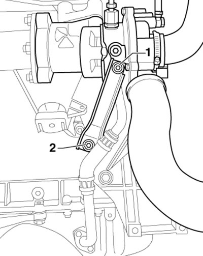
34.34. Turbocharger bracket fasteners
35. Place the cylinder head gasket on the centering pins in the cylinder block (the gasket number must be read from the inlet side). Place the cylinder head on the cylinder block and screw in all the new bolts by hand. Then tighten the cylinder head bolts in three steps in the sequence (1-10 in the illustration), at the first stage - with a force of 40 Nm, and at the second and third stages - tighten the bolts each time at an angle of 90°.
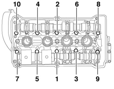
34.35. Cylinder head bolt tightening sequence
36. Further installation is carried out in the reverse order of dismantling the components. Use new bolts to secure the turbocharger to the exhaust manifold, tighten them with a force of 35 Nm. Tighten the turbocharger bracket fasteners to the compressor // cylinder block with a force of 30 // 25 Nm.
[This article was copied from the website: AUDImanual.ru]