
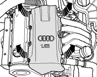
37.1. Removing the top engine cover
2. The radiator frame and alternator belt installation details are the same as on models with a 2.0 MPI engine (see Sections 6 and 7).
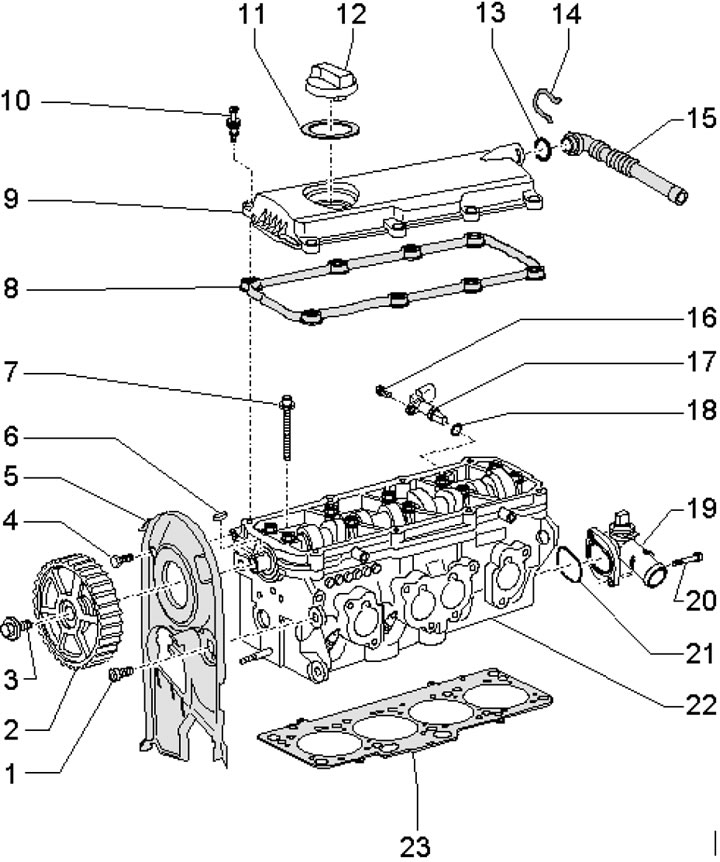
3. Timing belt installation details are shown in the illustration.
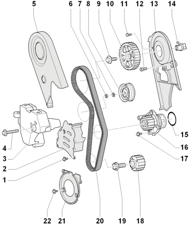
37.3. Timing Belt Installation Details 1. Cover fastening bolt 2, 10 Nm, installed on threaded varnish; 2. Timing belt center cover; 3, 4. Not used; 5. Upper timing belt cover, fastened to covers 2 and 13; 6. Roller mounting nut 8; 7. Washer; 8. Roller of semi-automatic belt tensioner 20; 9. Gear mounting bolt 10; 10. Camshaft gear wheel; 11. Cover fastening bolt 13, 10 Nm, installed on threaded varnish; 12. Cover fastening bolt 13, 23 Nm, installed on threaded varnish; 13. Rear timing belt cover; 14. Segment key for fastening gear wheel 10; 15. Sealing ring, subject to replacement; 16. Water pump; 17. Pump mounting bolt 16, 15 Nm; 18. Crankshaft gear; 19. Gear mounting bolt 18, 90 Nm, then tighten to an angle of 90°, use a new bolt; 20. Timing belt; 21. Timing belt lower cover; 22. Cover fastening bolt 21, 10 Nm, installed on threaded varnish
4. To install the piston of the first cylinder in the TDC position of the end of the compression stroke, the marks indicated in the illustrations must be aligned.
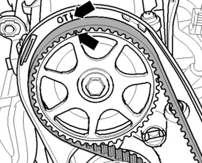
37.4a. BMT mark on the crankshaft
37.4b. BMT mark on camshaft
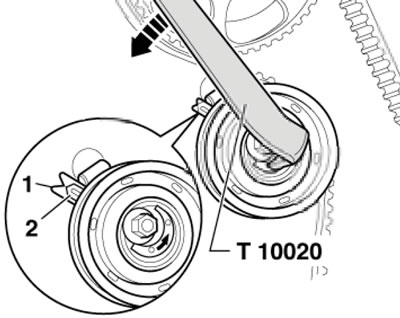
5. To tension the timing belt, first make sure that the tension roller tab enters the corresponding groove. Then turn the roller by the eccentric adjuster with key No. T10020 in the direction (arrows in the illustration) until it stops and loosen the tension until the pointer (2) is 10 mm below the mark (1). Repeat the steps in the previous sentence one more time and then tighten the belt so that the pointer (2) is opposite the mark (1). After tensioning, tighten the tension roller nut.
37.5. Tensioning the timing belt
6. The installation details of the crankshaft oil seals and their holders are the same as on models with a 2.0 MPI engine (see Section 11).
7. Major repairs are carried out in the same way as for 2.0 TFSI engines (see Section 28).
8. The details of installing the cylinder head and its cover are shown in the illustration. Unscrew the cylinder head and its cover mounting bolts in a diagonal order from the edges to the center, and tighten them in a diagonal order from the center to the edges. Tighten the cylinder head mounting bolts in four stages: first by hand, then with a force of 40 Nm, and then tighten twice to an angle of 90°.
37.8. Cylinder head and cover installation details 1. Cover fastening bolt 5, 23 Nm, installed on threaded varnish; 2. Camshaft gear wheel; 3. Gear wheel mounting bolt 2, 100 Nm; 4. Cover fastening bolt 5, 10 Nm, installed on threaded varnish; 5. Rear timing belt cover; 6. Segment key for fastening gear wheel 2; 7. Cylinder head mounting bolt 22, subject to replacement; 8. Cover gasket 9; 9. Cylinder head cover; 10. Special cover mounting bolt 9, 10 Nm; 11. Cover gasket 12; 12. Oil filler cap; 13. Tube sealing ring 15, subject to replacement; 14. Tube retaining clip 15; 15. PCV tube; 16. Bolt for fastening the CMP sensor 17; 17. SMR sensor; 18. Sealing ring of the CMP sensor 17; 19. Coolant pipe; 20. Pipe mounting bolt 19, 10 Nm; 21. Gasket, subject to replacement; 22. Cylinder head; 23. Cylinder head gasket (when replacing the gasket, replace the coolant)
9. Timing belt parts are shown in the illustration.
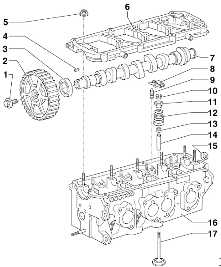
37.9. Timing belt parts 1. Gear wheel mounting bolt 2, 100 Nm; 2. Shaft gear 7; 3. Shaft seal 7, needs to be replaced; 4. Segment key for fastening gear wheel 2; 5. Cover fastening nuts 6, 23 Nm; 6. Shaft cover with built-in bearings, not subject to processing; 7. Camshaft; 8. Rocker; 9. Hydraulic valve clearance compensator; 10. Split lock crackers; 11. Spring plate 12; 12. Valve spring; 13. Oil deflector cap; 14. Valve guide bushing; 15. Rear plug of shaft 7; 16. cylinder head; 17. Valve, cannot be processed, only lapping
10. Camshaft cover fastening nuts (see illustration) tighten in the following sequence. First, tighten nuts 3-6 by hand in a diagonal sequence in several stages, then lightly tighten nuts 1, 2, 7-10, and finally tighten nuts 1-10 to 23 Nm.
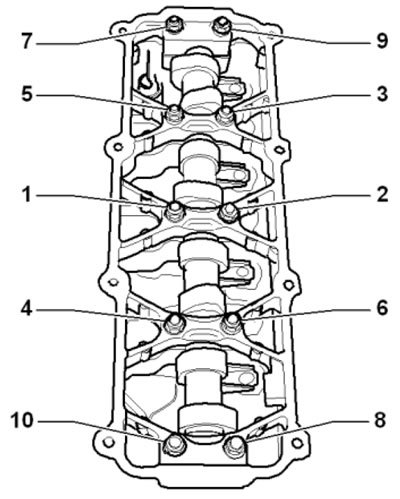
37.10. Camshaft cover fastening nuts
11. The position of the cams for cylinder No.1 of the camshaft, corresponding to TDC of piston No.1, is shown in the illustration. Install the shaft in this way before installing its cover.
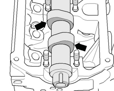
37.11. Position of the camshaft corresponding to TDC
12. The installation details of the oil pan, oil pump and oil level and temperature sensor are the same as for the 1.8T engine (see illustrations 36.1a,c). The installation details of the oil filter and oil cooler are shown in the illustration.
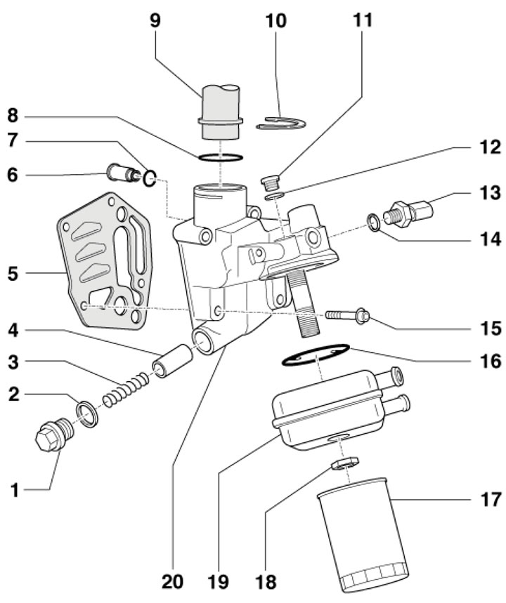
37.12. Oil filter and oil cooler installation details 1. Threaded plug, 40 Nm; 2. Sealing ring, subject to replacement; 3. 4 bar relief valve spring; 4. 4 bar relief valve piston; 5. Gasket, subject to replacement; 6. Retaining valve; 7. Sealing ring, subject to replacement; 8. Sealing ring, subject to replacement; 9. PCV tube; 10. Locking bracket; 11. Threaded plug, 15 Nm; 12. Sealing ring; 13. Oil pressure sensor 1.4 bar, 25 Nm; 14. Sealing ring; 15. Bracket mounting bolts 20, 15 Nm, then tighten to an angle of 90°, use new bolts; 16. Gasket, subject to replacement; 17. Oil filter, 20 Nm; 18 Nut, 25 Nm; 19. Oil cooler; 20. Filter bracket 17 with 4 bar bypass valve
[Read the original source on the website: AUDIMANUAL.ru]