
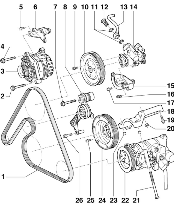
38.1. Generator Belt Installation Details 1. Generator drive belt; 2. Generator mounting bolt, 23 Nm; 3. Generator; 4. Generator mounting bolt, 45 Nm; 5. Bracket mounting bolt 6, 23 Nm; 6. Generator bracket; 7. Tensioner mounting bolt 8, 40 Nm; 8. Belt tensioner 1; 9. Pulley mounting bolt 10, 23 Nm; 10. Power steering pump pulley 14; 11. Sealing rings; 12. Hollow bolt, 47 Nm; 13. Power steering pressure line; 14. Power steering pump; 15. Power steering pump bracket 14; 16, 17. Bracket mounting bolt 15, 23 Nm; 18. Compressor holder 22; 19/20. Holder mounting bolt/nut 18, 23 Nm; 21. Compressor mounting bolt 22, 25 Nm; 22. Air conditioning compressor; 23. Centering sleeve; 24. Crankshaft pulley; 25. Pulley mounting bolt 24, 23 Nm; 26. Tensioner mounting bolt 8, 23 Nm
2. The installation details of the timing belt covers are shown in the illustration.
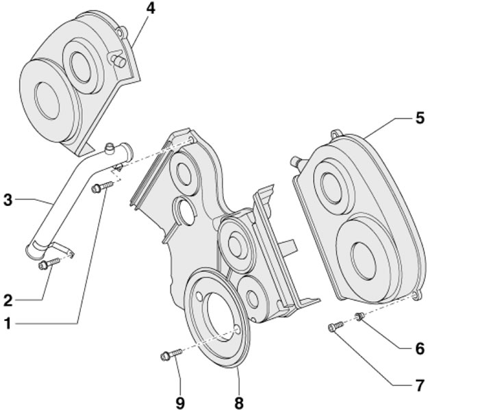
38.2. Timing Belt Cover Installation Details 1, 2. Tube mounting bolts 3, 10 Nm; 3. Front coolant supply pipe (to remove the covers, do not disconnect the hoses from it); 4/5. Front right/left timing belt cover; 6. Bushing; 7. Self-locking bolt, 6 Nm, must be replaced; 8. Lower timing belt cover; 9. Casing mounting bolt 8, 10 Nm
3. Timing belt installation details are shown in the illustration.
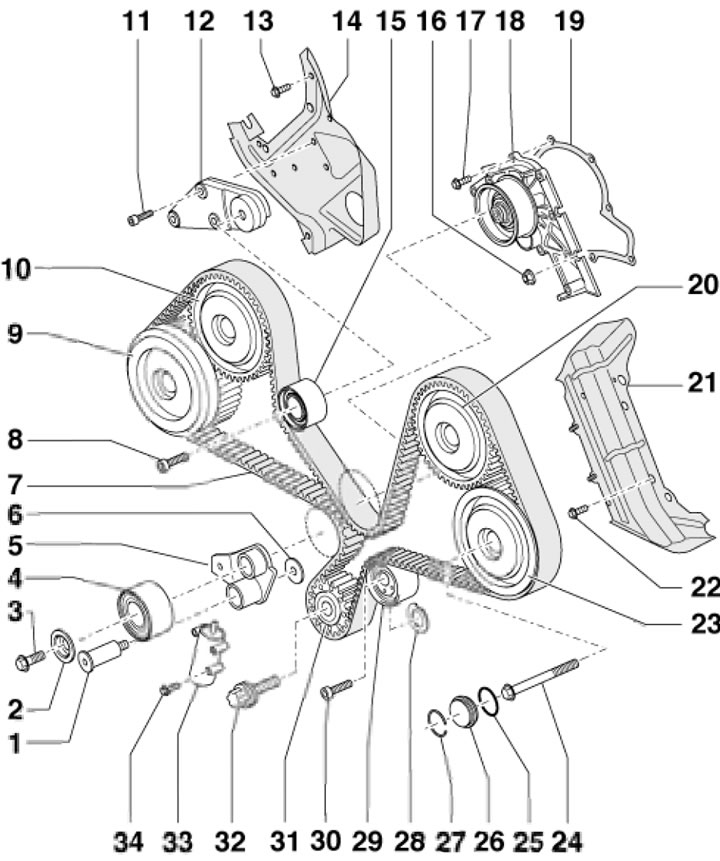
38.3. Timing Belt Installation Details 1. Self-locking bolt of the lever 5, 30 Nm, then tighten to an angle of 90°, subject to replacement; 2. Washer; 3. Self-locking bolt of roller 4, 30 Nm, then tighten to an angle of 90°, subject to replacement; 4. Tensioner roller 33; 5. Tensioner lever 33; 6. Lever washer 5; 7. Timing belt; 8. Roller mounting bolt 15, 45 Nm; 9. Toothed wheel with timing phase adjuster and "Auslass" marking (for the exhaust shaft of cylinder block No.1 (right)); 10. Toothed wheel with timing phase adjuster and marking "Einlass" (for intake shaft of cylinder block No.1 (right)); 11. Self-locking bolt of bracket 12, 10 Nm, subject to replacement; 12. Roller bracket 15; 13. Self-locking casing bolt 14, 10 Nm, subject to replacement; 14. Rear right timing belt cover; 15. Intermediate roller; 16/17. Pump mounting nut/bolt 18, 10 Nm; 18. Water pump; 19. Pump gasket 18, subject to replacement; 20. Toothed wheel with timing phase adjuster and marking "Einlass" (for intake shaft of cylinder block No.2 (left)); 21. Rear left timing belt cover; 22. Self-locking casing bolt 21, 10 Nm, subject to replacement; 23. Toothed wheel with timing phase adjuster and "Auslass" marking (for the exhaust shaft of cylinder block No.2 (left)); 24. Bolt for fastening gear wheel 23, 100 Nm; 25. Sealing ring, subject to replacement; 26. Bolt cover 24; 27. Retaining ring; 28. Washer (diamond coated) gear wheel 31, subject to replacement; 29. Intermediate roller with eccentric fastening; 30. Roller mounting bolt 29, 45 Nm; 31. Crankshaft gear; 32. Bolt for fastening the toothed wheel 31, 200 Nm, then tighten to an angle of 180°, subject to replacement; 33. Timing belt tensioner; 34. Tensioner mounting bolt 33.10 Nm
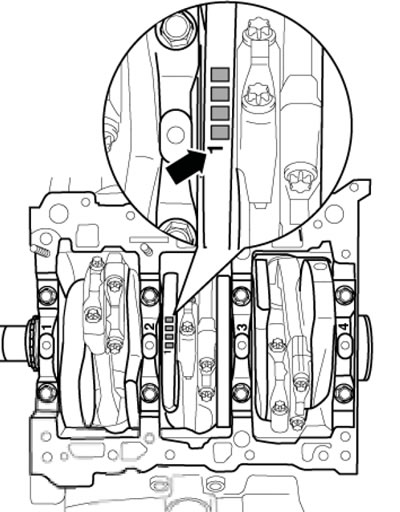
4. Marks for installing the piston of cylinder No.1 TDC position are shown in Illustration 38.4a. To fix the crankshaft in the TDC position, use device No. T40026, which is screwed into the cylinder block instead of the plug (see illustration 38.4b).
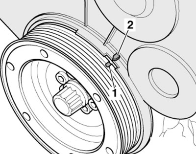
38.4a. TDC marks on the crankshaft pulley
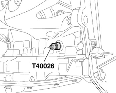
38.4b. Device for determining the TDC position and fixing the engine in this position
5. The installation details of the crankshaft and flywheel/drive plate seals are shown in the illustration. Tighten the 22.5 mm flywheel/drive plate mounting bolts to 60 Nm, then tighten through 90°. Tighten the 35 or 43 mm bolts to 60 Nm, then tighten through 180°. Press the needle bearing to a depth of 0.5 mm relative to the plastic flywheel ring.
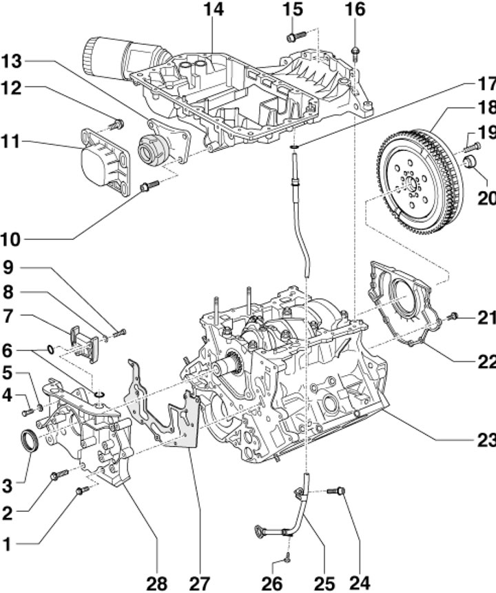
38.5. Crankshaft and Flywheel/Drive Disc Seal Installation Details 1. Holder mounting bolt 28, 10 Nm; 2. Self-locking bolt for mounting the holder 28, 30 Nm, subject to replacement; 3. Front crankshaft oil seal; 4. Cap bolt, 10 Nm; 5, 6. Sealing ring, subject to replacement; 7. Chain tensioner; 8. Washer; 9. Tensioner mounting bolt, 12 Nm; 10. Support mounting bolt 13; 11. Support stop 13; 12. Bolt for fastening the stop 11, 28 Nm; 13. Reactive support of the power unit; 14. Upper section of the engine oil pan; 15. Section fastening bolt 14, 45 Nm; 16. Bolts M7 and M8 for fastening sections 14, 16 and 22 Nm respectively; 17. Sealing ring, subject to replacement; 18. Flywheel or drive disk; 19. Special flywheel/drive disc mounting bolts, subject to replacement; 20. Needle bearing (on models with AT 01V a centering washer is installed instead); 21. Holder mounting bolt 22; 22. Rear oil seal holder (replaced together with the seal); 23. Cylinder block; 24. Tube mounting bolt 25; 25. Oil level dipstick tube; 26. Self-tapping screw; 27. Gasket, subject to replacement; 28. Seal holder 3
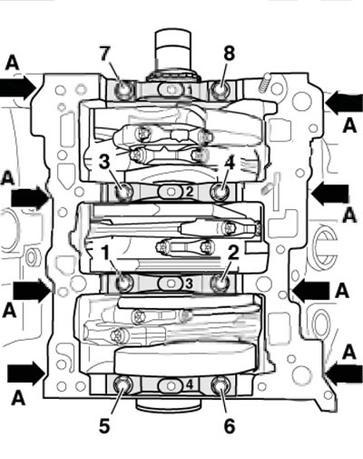
6. The crankshaft installation details are shown in the illustration. The numbering of the main bearing caps starts from the timing drive side.
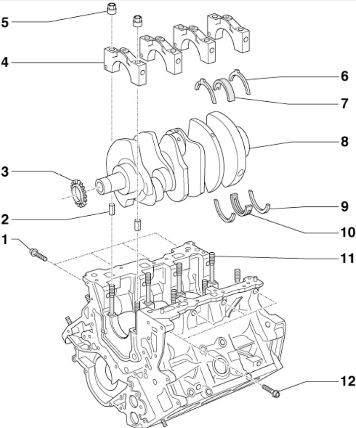
38.6. Crankshaft installation details 1. The support cover mounting bolts must be replaced; 2. Mounting sleeve; 3. Crankshaft sprocket; 4. Main bearing cap; 5. Cover fastening nuts 4, subject to replacement; 6. Adjusting washer on the 4th main bearing, installed with grooves facing outward; 7. Main bearing shell in cover 4 (without groove); 8. Crankshaft; 9. Adjusting washer on the 4th main bearing, installed with grooves facing outward; 10. Main bearing shell in the cylinder block (with a groove); 11. Expansion bolt; 12. The support cover mounting bolts must be replaced
7. The main bearing shells are marked with colored dots. To select the main bearing shell installed in the cylinder block, use the letter code near the corresponding main bearing (see illustration 38.7a): G - yellow, B - blue, S - black. To select the main bearing shell installed in the cover, use the letter code shown in Illustration 38.7b: G - yellow, B - blue, S - black.
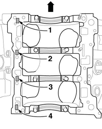
38.7a. Color marking codes for main bearing shells (for cylinder block)
38.7b Main Bearing Shell Color Codes (for lids)
8. To tighten the fasteners (see illustration) main bearing caps, proceed as follows. Insert both installation sleeves into the cylinder block and screw in new bolts (A) by hand. Tighten new bolts 1-8 to 35 Nm and tighten them to an angle of 90°. Tighten bolts A to 20 Nm and tighten them to an angle of 90°. The connecting rods should be installed so that the toes on the ground lower surfaces of connecting rod caps 1/2, 3/4 and 5/6 are facing each other.
38.8. Fastening the main bearing caps
9. Piston installation details are shown in the illustration.
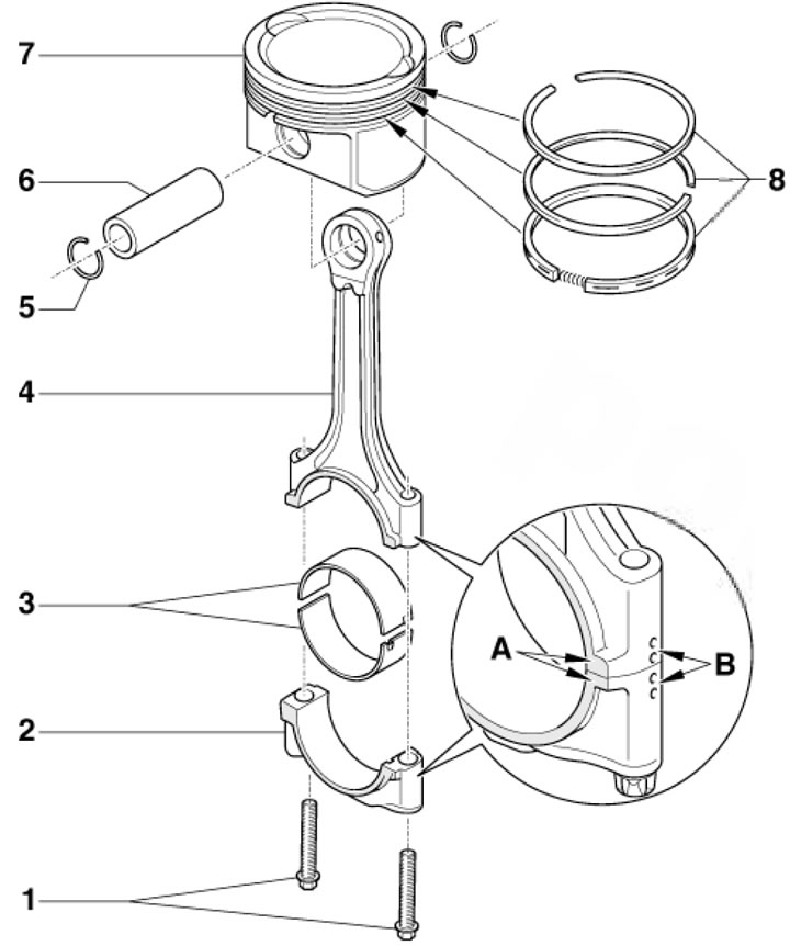
38.9. Piston mounting parts1. Cover mounting bolts 2, 30 Nm, then tighten to an angle of 90°,; are subject to replacement; 2. Connecting rod bearing cap with connecting rod combination mark (B) and matching projections (A); 3. Connecting rod bearing shells; 4. Connecting rod with marks (see point 2); 5. Pin retaining ring 6; 6. Piston pin; 7. Piston, arrow facing forward; 8. Piston rings (mark "TOP" facing up)
10. Details of installation of the cylinder head and its cover (using the example of the left cylinder head) are shown in the illustration. Loosen the cylinder head and cover mounting bolts diagonally from the edges to the center, and tighten them diagonally from the center to the edges. Tighten the cylinder head mounting bolts in four stages: first by hand, then with a force of 40 Nm, and then tighten twice to an angle of 90°.
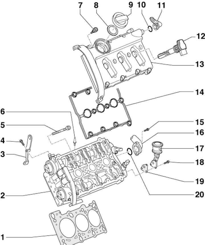
38.10. Left cylinder head installation details1. Cylinder head gasket; 2. Cylinder head (when replacing, replace the coolant); 3. Lifting eye; 4. Bolt for fastening eye 3; 5. Cylinder head mounting bolt, subject to replacement; 6. Intake manifold centering pin; 7. Special bolt for fastening the cylinder head cover, 10 Nm; 8. Cover gasket 9; 9. Oil filler cap; 10. Sealing ring, subject to replacement; 11. PCV hose; 12. Ignition coil; 13. Cylinder head cover; 14. Cover gasket 13; 15. Tube mounting bolt 16, 10 Nm; 16. Rear coolant supply pipe; 17. SAI combination valve; 18. Valve mounting bolt 17; 19. Gasket, subject to replacement; 20. Sealing ring, subject to replacement
11. Timing belt installation details (using the example of the left cylinder head) are shown in the illustration.
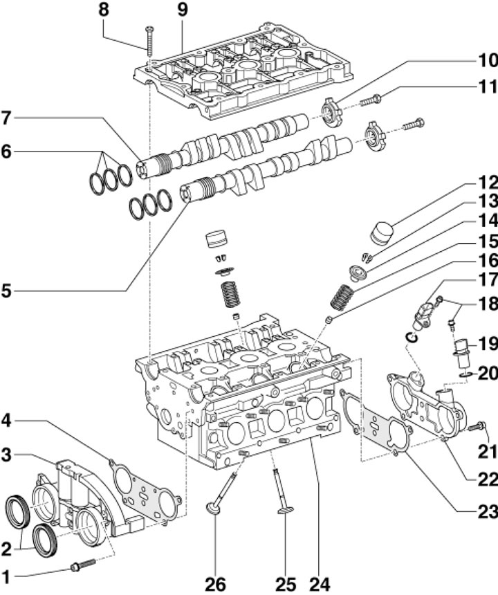
38.11. Timing belt installation details for left cylinder head1. Housing mounting bolt, 10 Nm; 2. Sealing rings are subject to replacement; 3. Housing of electromagnetic valves for adjusting the timing phases; 4. Gasket, subject to replacement; 5. Exhaust camshaft; 6. Piston rings of the timing phase regulators; 7. Intake camshaft; 8. Cover fastening bolt 9, 10 Nm; 9. Camshaft cover with built-in bearings; 10. SMR sensor rotor; 11. Rotor mounting bolt 10; 12. Hydraulic valve clearance compensator; 13. Split valve lock crackers; 14. Spring plate 15; 15. Valve spring; 16. Oil deflector cap; 17. SMR shaft 7 sensor; 18. Bolts for fastening sensors CMP 17 and 19; 19. SMR shaft 5 sensor; 20. Sealing ring, subject to replacement; 21. Housing mounting bolt 22, 10 Nm; 22. Housing of sensors SMR 17 and 19; 23. Housing gasket 22, subject to replacement; 24. Cylinder head; 25. Inlet valve; 26. Exhaust valve
12. Timing phase adjustment mechanism installation details (using the example of the left cylinder head) are shown in the illustration.
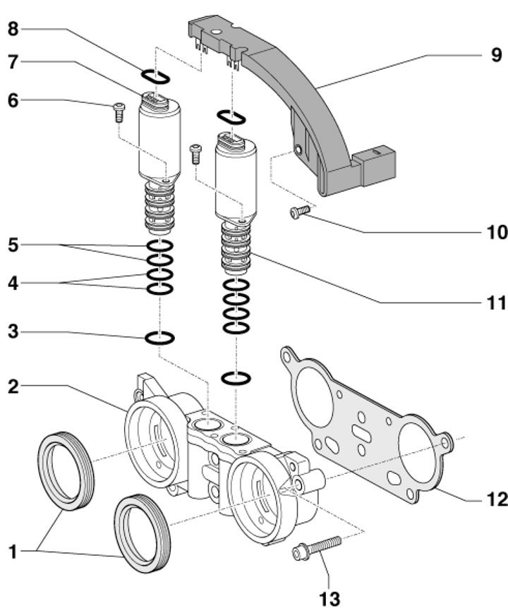
38.12. Timing phase adjustment mechanism installation details1. Sealing rings are subject to replacement; 2. Housing of electromagnetic valves 7 and 11; 3/4/5.Green/black/green sealing rings, subject to replacement; 6. Valve mounting bolt 7.4 Nm; 7. Solenoid valve for adjusting the timing phases of the intake side (marking 12.100 338); 8. Gasket; 9. Connector adapter; 10. Adapter mounting bolt 9.4 Nm; 11. Solenoid valve for adjusting the timing phases of the exhaust side (marking 12.100 339); 12. Gasket, subject to replacement; 13. Housing mounting bolt 2, 10 Nm
13. The installation details of the lower section of the oil pan and the oil pump are shown in the illustration.
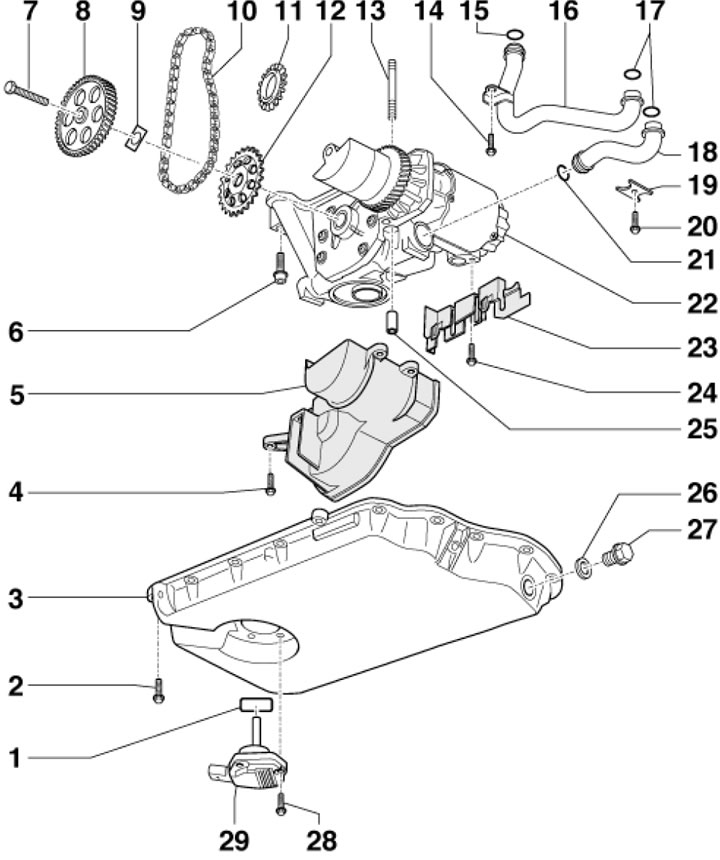
38.13. Installation details of the lower section of the oil pan and oil pump1. Gasket, subject to replacement; 2. Pan mounting bolt 3, 10 Nm; 3. Oil pan (lower section; 4. Bolt for fastening the damper 5; 5. Front oil separator; 6. Pump mounting bolt 22, 22 Nm, subject to replacement; 7. Sprocket mounting bolt 8, 20 Nm, then tighten to an angle of 90°, subject to replacement; 8. Balance shaft drive gear; 9. Washer (diamond coated), subject to replacement; 10. Pump drive chain 22; 11. Pump drive sprocket 22; 13. Self-locking stud, installed with the short side towards the cylinder block; 14. Tube mounting bolt 16; 15. Sealing ring, subject to replacement; 16. Oil pipe; 17. Sealing rings, subject to replacement; 18. Oil pipe; 19. Oil pipe bracket; 20. Bracket mounting bolt 19, 10 Nm; 21. Sealing ring; 22. Oil pump with balance shaft; 23. Rear oil separator; 24. Self-locking bolt of the damper 23, 10 Nm, subject to replacement; 25. Bushing, 20 Nm, then tighten to an angle of 120°, should be replaced; 26. Sealing ring, subject to replacement; 27. Drain plug thread, 30 Nm; 28. Sensor mounting bolt 29, 10 Nm; 29. Engine oil level and temperature sensor
14. The installation details of the upper section of the oil pan, oil filter and chain tensioner are shown in the illustration.
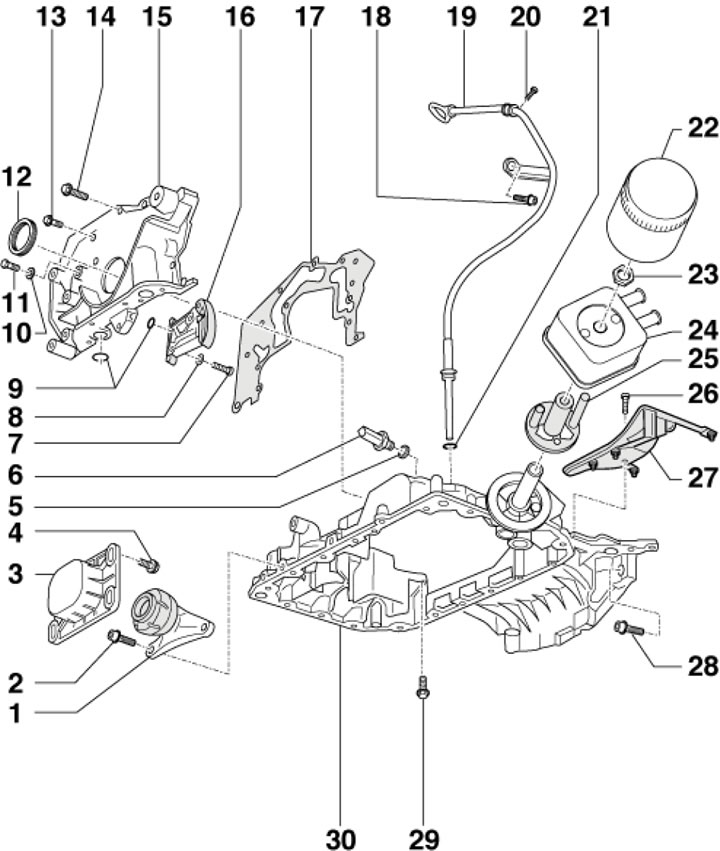
38.14. Installation details of the upper section of the oil pan, oil filter and chain tensioner 1. Reactive support of the power unit; 2. Support mounting bolt 1, 40 Nm; 3. Support stop 1; 4. Bolt for fixing the stop 3, 28 Nm; 5. Sealing ring; 6. Oil pressure sensor, 25 Nm; 7. Chain tensioner mounting bolt, 12 Nm; 8. Washer; 9, 10. Sealing rings, subject to replacement; 11. Plug bolt, 10 Nm; 12. Front crankshaft oil seal; 13. Holder mounting bolt 15, 10 Nm; 14. Self-locking cover mounting bolt 15, 10 Nm, subject to replacement; 15. Seal holder 12; 16. Oil pump chain tensioner; 17. Gasket, subject to replacement; 18. Tube mounting bolt 19, 20 Nm; 19. Oil level dipstick guide tube; 20. Self-tapping screw; 21. Sealing ring, subject to replacement; 22. Oil filter, 20 Nm; 23. Nut, 30 Nm; 24. Oil cooler; 25. Guide piece with seal; 26. Self-locking bolt for fastening the oil separator 27, 10 Nm, subject to replacement; 27. Upper oil separator; 28. Section fastening bolt 30, 45 Nm; 29. Bolts M7 and M8 for fastening sections 30, 16 and 23 Nm respectively; 30. Upper section of the oil pan