
Table of contents: Replacing the exhaust shaft seal ↓ Replacing the intake shaft seal ↓ Camshafts and chain tensioner ↓ Timing belt repair ↓
1. The valve drive mechanism parts are shown in the illustration.
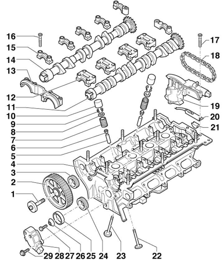
35.1. Timing belt parts 1. Gear wheel mounting bolt 2, 65 Nm; 2. Shaft gear 14; 3. Shaft seal 14; 4. Cylinder head; 5. Valve guide bushing; 6. Oil deflector cap; 7. Valve spring; 8. Upper spring plate 7; 9. Split valve lock crackers; 10. Hydraulic valve clearance compensator; 11. Intake camshaft; 12. Shaft bearing caps 11; 13. Front bearing covers of both shafts; 14. Exhaust camshaft; 15. Shaft bearing caps 14; 16. Cover fastening bolts 15, 10 Nm; 17. Bolts for fastening the mechanism 19, 10 Nm; 18. Shaft drive chain 11; 19. Timing phase adjustment mechanism with shaft adjustment valve 11; 20. Rubber-metal gasket; 21. Seal, subject to replacement; 22. Exhaust valve; 23. Inlet valve; 24. Shaft seal 11; 25. SMR sensor rotor (28); 26. Conical washer; 27. Oil seal mounting bolt 24, 25 Nm; 28. SMR sensor housing; 29. Housing mounting bolt 28, 10 Nm
Replacing the exhaust shaft seal
2. Install the radiator frame in the service position (see Section 30).
3. Remove the timing belt from the camshaft sprocket (see Section 32).
4. Holding the camshaft gear from turning with tool #3306, unscrew the central bolt and remove the gear (see illustration 14.4).
5. Screw the gear mounting bolt into the camshaft by hand. Unscrew the inner part of the seal puller No.2085 by 2 turns (by about 3 mm) from the outer part and secure with a knurled bolt. Lubricate the threaded head of the puller with engine oil, install it and, pressing hard, screw it as deep as possible into the seal (see illustration 14.5). Loosen the knurled bolt and rotate the inner part against the camshaft until the seal is removed. Clamp the flats of the removed puller in a vice and remove the seal with pliers.
6. Place guide sleeve No. T10071/1 on the camshaft journal (see illustration 14.6). Without lubricating the working edge of the seal, put it through the guide sleeve onto the shaft journal, then remove the guide sleeve.
7. Press the oil seal using sleeve No. T10071/3 and bolt No. T10071/4 until it stops (see illustration 14.7).
8. Install the camshaft gear so that the narrow web of the gear faces outward (arrows in illustration 14.8), and the TDC mark of cylinder No.1 was visible.
9. While holding the gear wheel from turning, tighten its mounting bolt.
Caution: When turning the camshaft with the timing belt removed, none of the pistons should be at TDC.
10. Install the timing belt (see Section 32).
11. Further installation is carried out in the reverse order of dismantling the components.
Replacing the intake shaft seal
12. Remove the decorative (upper) engine cover upwards (see illustration 29.9), remove the upper timing belt cover from the clamps.
13. Disconnect the CMP sensor connector (see illustration 14.15) and remove the sensor housing with the washer and rotor.
14. Perform the actions described in paragraphs 18-22 Section 14.
Camshafts and chain tensioner
15. Set the radiator frame to the service position (see Section 30).
16. Remove the timing belt from the camshaft sprocket (see Section 32).
17. Turn the crankshaft by the pinion bolt at an angle of approximately 45° counterclockwise so that none of the pistons is at TDC.
18. Holding the camshaft gear from turning with tool #3306, unscrew the central bolt and remove the gear (see illustration 14.4).
19. Disconnect the intake camshaft adjustment valve connector (see illustration 34.20).
20. Remove the cylinder head cover (see Section 34) and both oil distributors (3 in illustration 34.1).
21. Disconnect the CMP sensor connector (see illustration 14.15) and remove the sensor housing with the washer and rotor.
22. Check again that the camshafts are in the TDC position. The two marks on the camshafts should be located opposite the arrows on the camshaft bearing caps (see illustration).
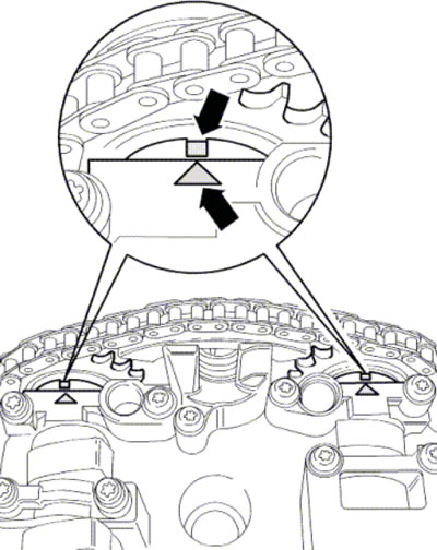
35.22. TDC marks on camshafts
23. If the removed intake camshaft drive chain is intended to be reused, clean it and the camshaft sprockets in the areas opposite both TDC arrows and mark the installation position of the chain relative to the sprockets with a felt-tip pen (see illustration 14.33). The distance between the two marks corresponds to 16 chain rollers. The notch on the outlet shaft is offset inward relative to the chain roller (1).
24. Secure the hydraulic chain tensioner using clamp #3366 (see illustration).
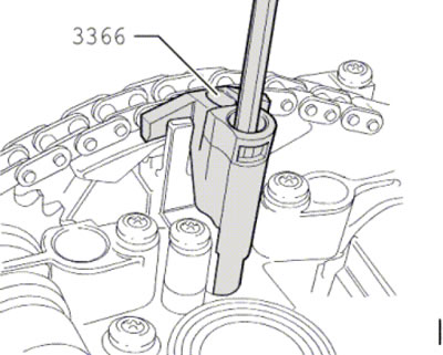
35.24. Fixing the chain tensioner
Note: Overtightening the chain tensioner bracket may damage the tensioner.
25. Unscrew the bearing cap mounting bolts No.3 and No.5 on both shafts (see illustration). Remove the double bearing cap, then remove the two caps near the sprockets. Unscrew the camshaft adjuster mounting bolts, loosen bearing caps #2 and #4 of both shafts in a diagonal sequence and remove caps #2 and #4. Remove the shafts with the adjuster.
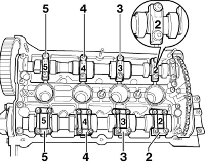
35.25. Camshaft bearing caps
26. Make sure the pistons are not at TDC. Install a new rubber-metal gasket (20 in illustration 35.1) and apply a thin layer of sealant to the area shown in the illustration.
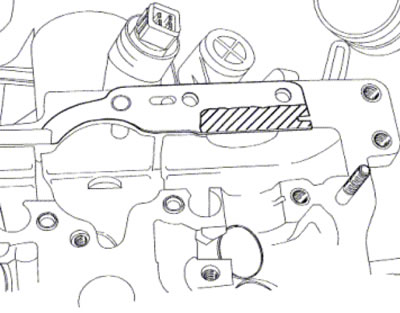
35.26. Area of sealant application
27. Position the chain on the camshaft sprockets. If using a removed chain, align the marks made during removal (see illustration 35.23). If a new chain is used, the distance between the marks (A and B in the illustration)on the camshafts there should be 16 chain rollers (the illustration shows where rollers 1 and 16 should be installed on the sprockets; mark (A) relative to the chain roller (1) is shifted inward).
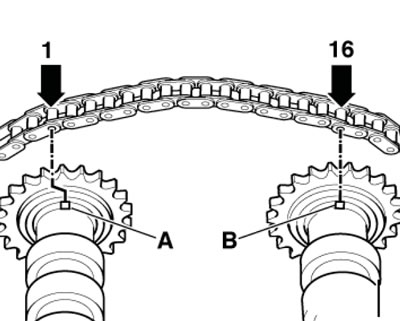
35.27. Position of the new chain on the sprockets
28. Together with an assistant, insert the camshaft adjuster into the chain, lay the camshafts (with chain and regulator) into the cylinder heads and lubricate the working surfaces of the shafts.
29. Make sure the cylinder head has dowel pins for the bearing caps and camshaft adjuster.
30. Secure the camshaft adjuster and tighten the fasteners of covers No.2 and No.4 of both camshafts in a diagonal sequence.
Note: The marks on the covers must be read from the intake side. Install the covers of both shafts near the sprockets and remove the chain retainer (see illustration 35.24).
31. Check the correct position of the camshafts: both marks on the shafts should be opposite both arrows on the bearing cap (see illustration 35.22). To ensure that both marks match, you should, if necessary, move the shafts slightly in one direction or another.
32. Apply a small amount of sealant to the areas shown in the illustration on the double cover and the outer cover adjacent to the camshaft adjuster.
33. Install the remaining bearing caps, new camshaft seals and tighten the bearing cap fasteners.

35.32. Places of sealant application
34. Install the camshaft gear so that the narrow web of the gear faces outward (arrows in illustration 14.8), and the TDC mark of cylinder No.1 was visible.
35. While holding the gear wheel from turning, tighten its mounting bolt.
Caution: When turning the camshaft with the timing belt removed, none of the pistons should be at TDC.
36. Install the CMP sensor and cylinder head cover (see Section 34).
37. Turn the crankshaft by the bolt of its pulley at an angle of approximately 45° clockwise to set the pistons to TDC. Install the timing belt (see Section 32).
38. Further installation is carried out in the reverse order of dismantling the components.
39. After installing the camshafts, the engine must not be started for approximately 30 minutes. The hydraulic compensators must be settled (otherwise the valves will touch the pistons). After working on the valve train, turn the crankshaft by hand at least two revolutions to ensure that no valve is in contact with the piston.
Timing belt repair
Attention: It is prohibited to modify the intake and exhaust valves; only lapping is allowed.
40. To replace the oil-deflecting caps, special devices are used that allow you to squeeze out the valve spring and remove the crackers of the split valve lock (see illustration 35.1). If the procedure is performed with the cylinder head installed, supply compressed air at a pressure of at least 6 bar to the combustion chamber through the spark plug hole.
41. Checking hydraulic compensators and valve guide bushings, as well as processing valve seats are described in Section 15.