



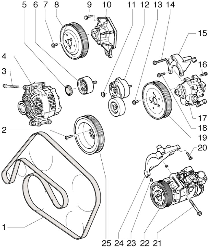
39.1. Generator Drive Belt Installation Details1. Generator drive belt; 2. Pulley mounting bolt 25, 20 Nm, then tighten to an angle of 90°, subject to replacement; 3. Generator mounting bolt, 22 Nm; 4. Generator; 5. Pulley cover 6; 6. Intermediate roller, 40 Nm; 7. Pulley mounting bolt 8, 20 Nm; 8. Water pump pulley; 9. Pump mounting bolt 10.9 Nm; 10. Water pump; 11. Tensioner plug; 12. Belt tensioner 1, 40 Nm; 13. Pulley mounting bolt 19, 20 Nm; 14. Bracket mounting bolt 15, 20 Nm; 15. Power steering pump bracket; 16. Power steering pump mounting bolt 20 Nm; 17. Power steering pump; 18. Bracket mounting bolt 15, 20 Nm; 19. Power steering pump pulley with the "Front" marking; 20. Bracket mounting bolt 24, 20 Nm; 21. Compressor mounting bolt 22, 25 Nm; 22. Air conditioning compressor; 23. Centering sleeve; 24. Compressor bracket 22; 25. Crankshaft pulley
2. Flywheel/drive disc installation details are shown in the illustrations.
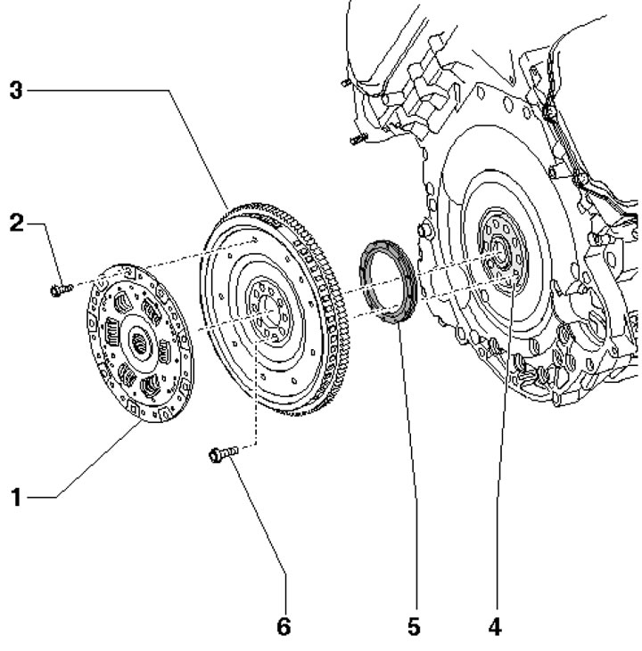
39.2a. Flywheel installation details for CVT models1. Torsional vibration damper; 2. Damper mounting bolts 1, 22 Nm; 3. Flywheel; 4. Crankshaft; 5. Rear crankshaft oil seal, subject to replacement; 6. Flywheel mounting bolts, 60 Nm, then tighten to an angle of 90°, subject to replacement
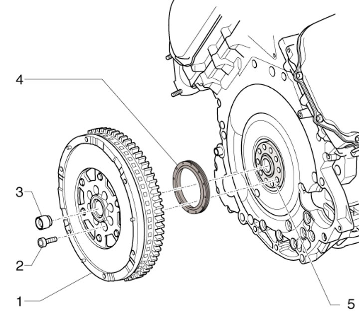
39.2b. Installation details of dual mass flywheel for models with manual transmission1. 2-mass flywheel; 2. Flywheel mounting bolts 1, 60 Nm, then tighten to an angle of 90°, subject to replacement; 3. Needle bearing; 4. Rear crankshaft oil seal, subject to replacement; 5. Crankshaft
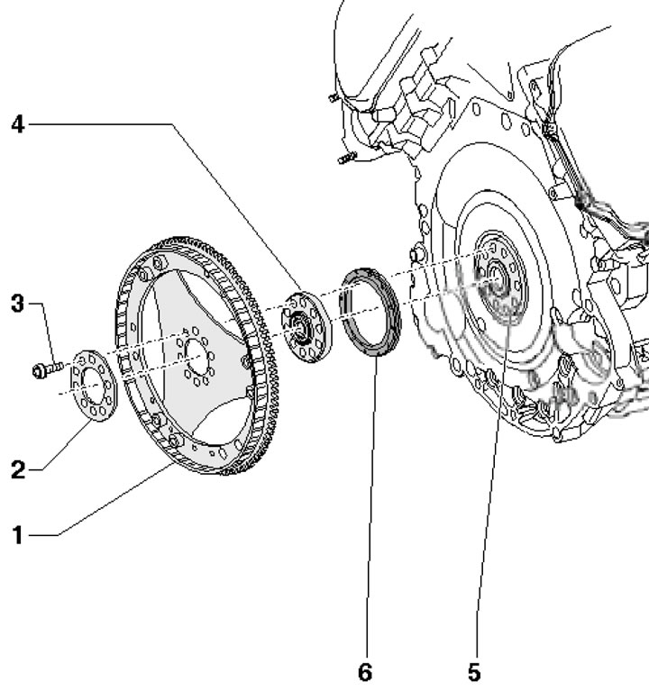
39.2s. Drive Disc Installation Details for Models with AT 09L 1. Drive disk; 2. Adjusting plate; 3. Disc mounting bolts 1, 60 Nm, then tighten to an angle of 90°, subject to replacement; 4. Centering washer; 5. Crankshaft; 6. Rear crankshaft oil seal, subject to replacement
3. The connecting rod and piston group parts are shown in the illustration. The connecting rods should be installed so that the toes on the ground lower surfaces of the connecting rod caps 1/2, 3/4 and 5/6 are facing each other.
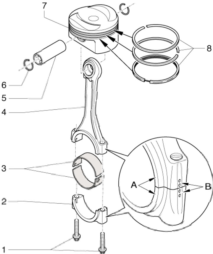
39.3. Connecting rod and piston group parts1. Cover fastening bolt 2, 30 Nm, then tighten to an angle of 90°, subject to replacement; 2. Bearing cover 3 with connecting rod attachment marks (B) and flange (A) for mating with the connecting rod; 3. Connecting rod bearing shells (the top one is lighter); 4. Connecting rod with marks corresponding to cover 2; 5. Piston pin; 6. Retaining ring, subject to replacement; 7. Piston; 8. Piston rings (installed with the "TOP" mark facing up)
4. The crankshaft installation details are shown in the illustration.
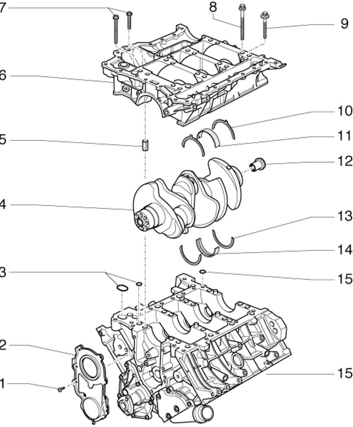
39.4. Crankshaft installation details 1. Flange mounting bolts 2.9 Nm; 2. Front crankshaft oil seal flange, subject to replacement; 3. Gaskets are subject to replacement; 4. Crankshaft; 5. Centering bushings; 6. Shaft frame 4; 7. Frame mounting bolts 6 (see illustration 39.5); 8. Extended bolt for inner row of frame 6 (see illustration 39.5); 9. Shortened bolt for outer row of frame 6 (see illustration 39.5); 10. Adjusting washers on the 3rd main bearing; 11. Main bearing shell for frame 6; 12. Centering washer (only models with AT 09L); 13. Adjusting washer on the 3rd main bearing; 14. Main bearing shell for block 16; 15. Sealing ring, subject to replacement; 16. Cylinder block
5. Tighten the crankshaft frame mounting bolts in accordance with the accompanying illustration in the following sequence. Screw new long bolts into the inner row of the frame, tighten the bolts (1-16) with a force of 50 Nm, and then tighten to an angle of 90°. Tighten the bolts in the sequence (17-31) with a force of 23 Nm.
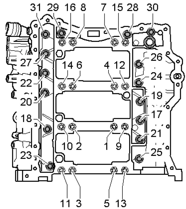
39.5. Crankshaft frame mounting bolts
6. To select the main bearing shell (by color coding), installed in the cylinder block, a letter code is used near the corresponding main bearing (see illustration). On engines with numbers up to AUK 028 000 and 033 000, the following codes are used for bearings No.1 // No.2-4: G - red I yellow, B - yellow // blue, S - blue // black. On engines with numbers from AUK 028 001 and 033 001, the following codes are used for all bearings: R - red, G - yellow, B - blue, S - black.
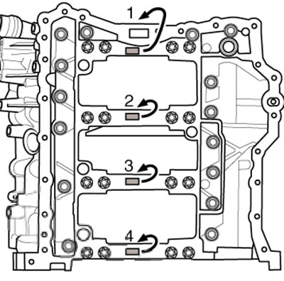
39.6. Marking code of main bearings for cylinder block
7. To select the main bearing shell (by color coding), installed in the cover, the letter code shown in the illustration is used. The application of the codes is the same as for the liners installed in the cylinder block (see paragraph 6).
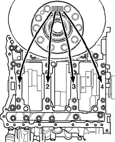
39.7. Main bearing marking code for caps
8. The details of the balance shaft installation are shown in the illustration.
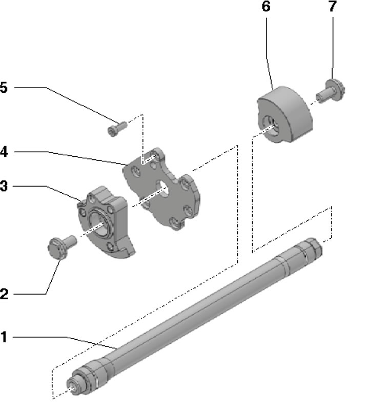
39.8. Balance shaft installation details 1. Balance shaft; 2/7. Counterweight mounting bolt 3/6, 60 Nm; 3. Counterweight on the chain drive side; 4. Bearing shield; 5. Shield mounting bolt 4, 13 Nm; 6. Counterweight on the pulley side
9. The installation details of the balance shaft drive chain and oil pump are shown in the illustrations.
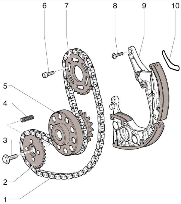
39.9a. Balance shaft and oil pump drive chain installation details (models up to 04.2006) 1. Chain; 2. Oil pump sprocket; 3. Sprocket mounting bolt 2, 30 Nm, then tighten to an angle of 90°, subject to replacement; 4. Spring; 5. Crankshaft; 6. Sprocket mounting bolt 7, 15 Nm, then tighten to an angle of 90°, subject to replacement; 7. Balance shaft sprocket (installed with the side with the inscription facing the transmission); 8. Tensioner mounting bolt 9.6 Nm, then tighten to an angle of 45°, subject to replacement; 9. Chain tensioner 1 with a guide bar; 10. Gasket, subject to replacement
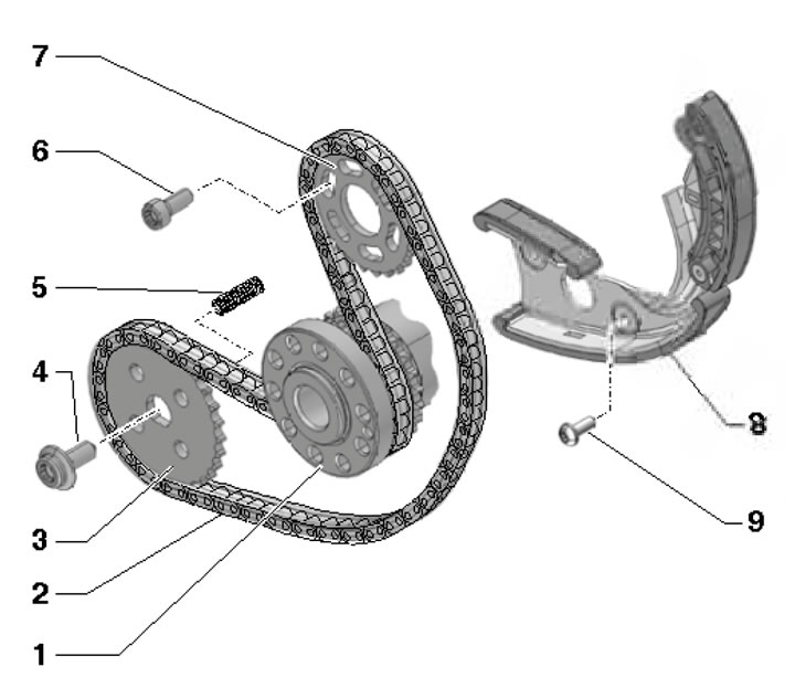
39.9b Balance shaft and oil pump drive chain installation details (models from 04.2006) 1. Crankshaft; 2. Chain; 3. Oil pump sprocket; 4. Sprocket mounting bolt 3, 30 Nm, then tighten to an angle of 90°, subject to replacement; 5. Spring; 6. Sprocket mounting bolt 7, 15 Nm, then tighten to an angle of 90°, subject to replacement; 7. Balance shaft sprocket (installed with the side with the inscription facing the transmission); 8. Chain tensioner 2 with a guide bar; 9. Tensioner mounting bolt 8, 10 Nm, then tighten to an angle of 45°, subject to replacement
10. Timing chain drive parts are shown in the illustrations. Bolts (3, 8, 11, 19 and 27 in Illustration 39.10a) tighten to 10 Nm and then tighten to an angle of 30° (for bolts with pin) or 90° (for other type of bolts).
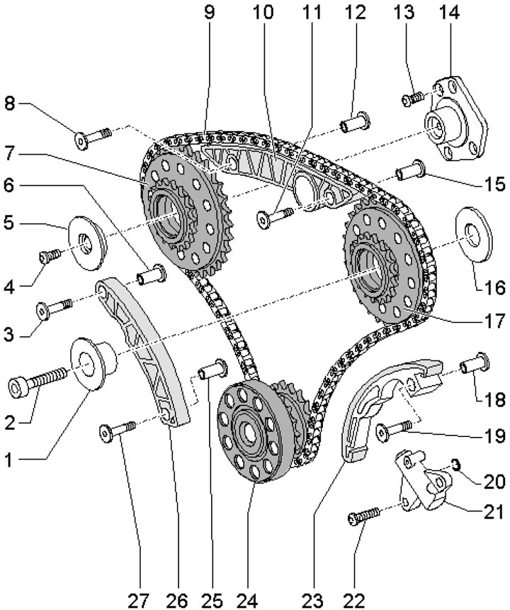
39.10a. Lower timing chain 1. Sprocket bracket 24; 2. Sprocket mounting bolt 17, 30 Nm, then tighten to an angle of 90°, subject to replacement; 3.27. Bolt for fastening bar 26, subject to replacement; 4. Sprocket mounting bolt 7.6 Nm, then tighten to an angle of 60°, subject to replacement; 5. Sprocket adjusting washer 7; 6. Bushing; 7. Timing drive sprocket of the left cylinder bank; 8, 11. Bolt for fastening bar 10, subject to replacement; 9. Lower timing chain; 10, 23, 26. Chain guide bar; 12,15. Bushing; 13. Bracket mounting bolt 14, 8 Nm, then tighten to an angle of 60°, subject to replacement; 14. Sprocket bracket 7; 16. Adjusting washer; 17. Timing drive sprockets of the right cylinder bank; 18, 25. Bushing; 19. Bolt for fastening bar 23, subject to replacement; 20. Sealing ring, subject to replacement; 21. Chain tensioner 9; 22. Tensioner mounting bolt 21, 6 Nm, then tighten to an angle of 45°, subject to replacement; 24. Crankshaft
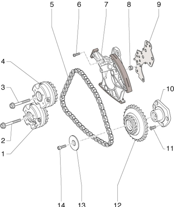
39.10b Upper left timing chain 1/4. Timing mechanism for adjusting the valve timing of the exhaust/intake shaft (with markings "Exaust"/"Intake"); 2/3. Mechanism mounting bolt 1/4, 40 Nm, then 80 Nm, then tighten to an angle of 90°, subject to replacement; 5. Left cylinder head shaft drive chain; 6. Tensioner mounting bolt 7.9 Nm; 7. Chain tensioner 5; 8. Mesh oil filter; 9. Gasket, subject to replacement; 10. Sprocket bracket 12; 11. Bracket mounting bolt 10.8 Nm, then tighten to an angle of 45°, subject to replacement; 12. Left cylinder head shaft drive sprocket; 13. Sprocket adjusting washer 12; 14. Sprocket mounting bolt 12.6 Nm, then tighten to an angle of 60°, subject to replacement

39.10s. Upper right timing chain 1. Sprocket of the right cylinder head shaft drive; 2. Sprocket support pin 1; 3. Sprocket mounting bolt 1, 30 Nm, then tighten to an angle of 60°, subject to replacement; 4. Left cylinder head shaft drive chain; 5/12. Bolt for fastening the mechanism 6/11, 40 Nm, then 80 Nm, then tighten to an angle of 90°, subject to replacement; 6/11. Timing mechanism for adjusting the valve timing of the exhaust/intake shaft (with marking "Intake"/"Exaust"); 7. Chain tensioner 4; 8. Mesh oil filter; 9. Gasket, subject to replacement; 10. Tensioner mounting bolt 7.9 Nm; 13. Sprocket adjusting washer 1
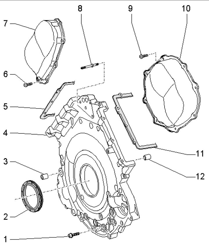
39.10d. Timing chain cover fastening parts1. Cover fastening bolt 4: M6 - 9 Nm, M8 - 20 Nm; 2. Crankshaft oil seal; 3, 12. Centering sleeve; 4. Lower timing chain cover (lower); 5/11. Left/right cylinder head gasket; 6/9. Cover fastening bolt 7/10, 5 Nm, then tighten to an angle of 90°, subject to replacement; 7/10. Left/right upper timing chain cover; 8. Hairpin (on models from 05.2005.), 16 Nm
11. The cylinder head installation details are shown in the illustration.
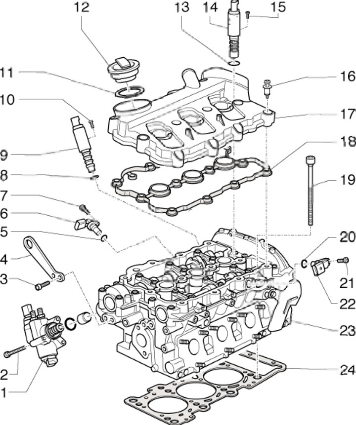
39.11. Cylinder head installation details1. Fuel injection pump; 2. Fuel injection pump mounting bolt 1.9 Nm; 3. Bolt for fastening eye 4; 4. Lifting eye; 5,8,13,20. Sealing ring, subject to replacement; 6/22. Intake/Exhaust Crankshaft Position Sensor; 7/21. Sensor mounting bolt 6/22, 8 Nm, then tighten to an angle of 90°, subject to replacement; 9/14. Solenoid valve for adjusting the timing phases of the intake/exhaust side 10/15 Valve mounting bolt 9/14, 2.5 Nm; 11. Gasket; 12. Oil filler cap; 16. Special cover mounting bolt 17.9 Nm; 17. Cylinder head cover 23; 18. Cover gasket 17; 19. Cylinder head mounting bolt 23; 23. Cylinder head; 24. Cylinder head gasket 23
12. The valve mechanism installation details are shown in the illustration.
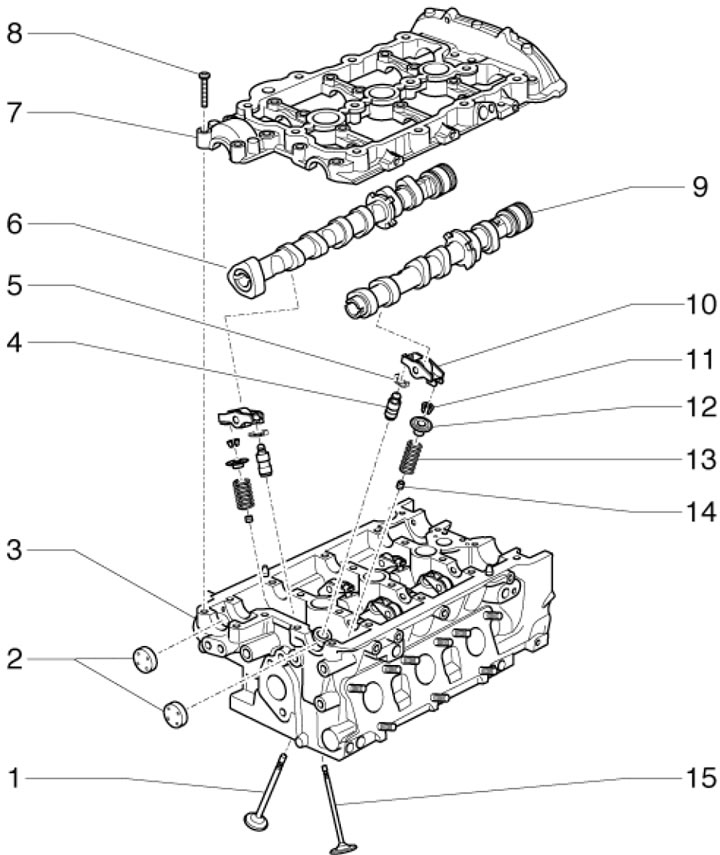
39.12. Valve Mechanism Parts 1/15. Exhaust/intake valve; 2. Plug; 3. Cylinder head; 4. Hydraulic compensator; 5. Safety bracket; 6/9. Inlet/outlet camshaft; 7. Camshaft cover with built-in bearings; 8. Cover fastening bolt 7.8 Nm, then tighten to an angle of 90°, use a new bolt; 10. Rocker; 11. Split valve lock crackers; 12. Spring plate 13; 13. Spring; 14. Oil deflector cap
13. The installation details of the upper section of the oil pan, oil pump and oil radiator are shown in the illustration.
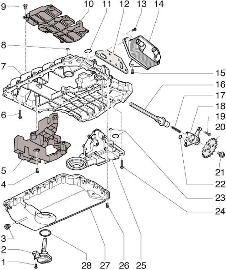
39.13. Details of installation of oil pan, oil pump and oil radiator. 1. Sensor mounting bolt 2.9 Nm; 2. Oil level and temperature sensor; 3. Drain plug, 30 Nm; 4. Oil separator mounting bolt 5.9 Nm; 5. Lower oil separator; 6. Section 7 mounting bolt, 16 Nm; 7. Upper section of the oil pan; 8. Sealing ring, subject to replacement; 9. Oil separator mounting bolt 10.9 Nm; 10. Upper oil separator; 11, 12. Gasket, subject to replacement; 13, 15. Oil cooler mounting bolt, 9 Nm; 14. Oil cooler; 16. Pump drive shaft 25; 17. Spring; 18. Bracket; 19. Bracket mounting bolt 18.9 Nm; 20. Oil pump sprocket; 21. Sprocket mounting bolt 20, 30 Nm, then tighten to an angle of 90°, subject to replacement; 22,23. Sealing ring, subject to replacement; 24. Pump mounting bolt 25; 25. Oil pump; 26. Section 27 fastening bolt, 9 Nm; 27. Lower section of the oil pan; 28. Sealing ring, subject to replacement
14. The details of the oil filter housing installation are shown in the illustrations.
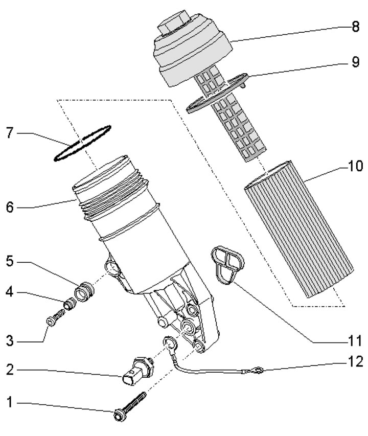
39.14a. Oil filter installation details (models produced before 04.2005.) 1, 3. Housing mounting bolt 6, 13 Nm; 2. Engine oil pressure sensor, 20 Nm; 4. Bushing; 5. Rubber tip; 6. Oil filter housing with 3.0 bar bypass valve; 7.9. Sealing ring, subject to replacement; 8. Oil filter cover, 25 Nm; 10. Filter element; 11. Gasket, subject to replacement; 12. O-ring with ground wire, subject to replacement
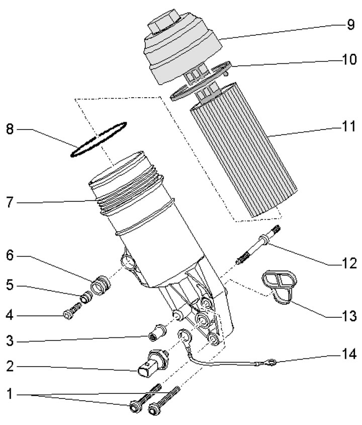
39.14b. Oil filter installation details (models from 05.2005.) 1.4. Housing mounting bolts 7, 13 Nm; 2. Engine oil pressure sensor, 20 Nm; 3. Nut, 13 Nm; 5. Bushing; 6. Rubber tip; 7. Oil filter housing with 3.0 bar bypass valve; 8,10. Sealing ring, subject to replacement; 9. Oil filter cover, 25 Nm; 11. Filter element; 12. Stud, 16 Nm; 13. Gasket, subject to replacement; 14. O-ring with ground wire, subject to replacement