
Table of contents: Removal and installation the oil pan ↓ Removal and installation the oil pump ↓ Removal and installation the oil… ↓
Note: If, during repairs, an increased amount of metal shavings or wear products in the engine oil are found in the engine, then to avoid subsequent damage, the lubrication channels should be thoroughly cleaned and the oil cooler should be replaced.
Note: Major repairs are carried out in the same way as for 2.0 TFSI engines (see Section 28).
1. The installation details of the lubrication system components are shown in the illustrations.
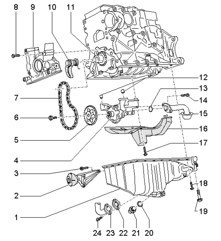
36.1a. Oil pan and oil pump1. Oil pan; 2. Powertrain support; 3. Support mounting bolt 2, 23 Nm; 4. Oil pump with 12 bar bypass valve; 5. Pump drive sprocket 4; 6. Sprocket mounting bolt 5, 22 Nm; 7. Pump drive chain 4; 8. Holder mounting bolts 9.15 Nm; 9. Front oil seal holder; 10. Chain tensioner 7, 16 Nm; 11. Crankshaft sprocket; 12. Guide bushings; 13. Sealing ring, subject to replacement; 14. Oil intake mounting bolts 15.; 15. Oil intake; 16. Oil soother; 17. Bolt for fastening the damper 16.16 Nm; 18. Pan mounting bolts 1, 15 Nm; 19. Pan mounting bolts 1, 40 Nm; 20. Sealing ring, subject to replacement; 21. Drain plug; 22. Gasket, subject to replacement; 23. Oil return pipe; 24. Tube mounting bolts 23, 10 Nm
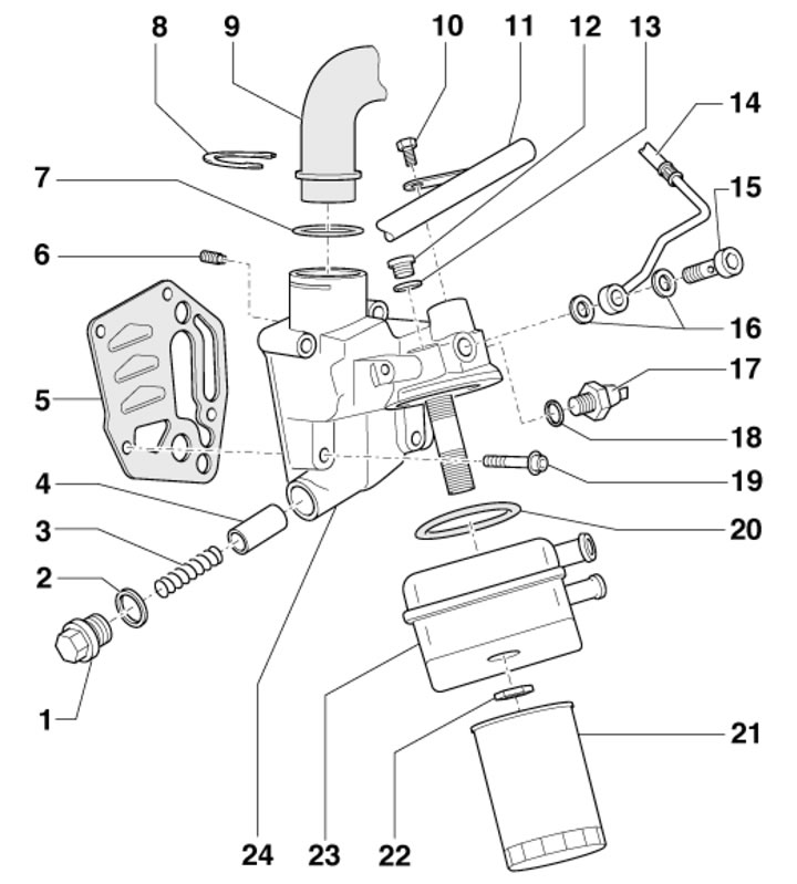
36.1b. Oil pump with balance shaft drive 1. Threaded plug, 40 Nm; 2. Sealing ring, subject to replacement; 3. 4 bar relief valve spring; 4. 4 bar relief valve piston; 5. Gasket, subject to replacement; 6. Retaining valve, built into the filter bracket, 8 Nm; 7. Sealing ring, subject to replacement; 8. Locking bracket; 9. PCV tube; 10. The bolt for fastening the tube 11, 20 Nm is installed on the varnish; 11. Coolant pipe (lower); 12. Threaded plug, 15 Nm; 13. Sealing ring; 14. Oil supply pipe to turbocharger; 15. Hollow bolt, 30 Nm; 16. Sealing rings, subject to replacement; 17. Oil pressure sensor 1.4 bar, 20 Nm; 18. Sealing ring; 19. Bracket mounting bolts 24.15 Nm, then tighten to an angle of 90°, use new bolts; 20. Sealing ring, subject to replacement; 21. Oil filter, 20 Nm; 22. Nut, 25 Nm; 23. Oil cooler; 24. Filter bracket 21 with 4 bar bypass valve
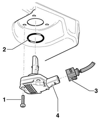
36.1s. Oil level and temperature sensor1. Self-locking bolt, 10 Nm, must be replaced; 2. Sealing ring, subject to replacement; 3. Electrical wiring connector; 4. Oil level and temperature sensor
Removal and installation the oil pan
2. Release the fasteners (arrows in illustration 29.9) and remove the top engine cover.
3. If there is a casing (1 in illustration 5.11) on the right side of the engine compartment, remove this cover.
4. Disconnect the EVAP valve solenoid connector (1 in illustration 5.12) and remove the electromagnetic valve. Unscrew the screws (arrows) and remove the air duct (2).
5. Mark the direction of rotation on the alternator belt with chalk or a felt-tip pen so that you can install the belt in the same way later. Loosen the belt tension by turning the tensioner in the direction of the arrow (see illustration 5.26), and remove it.
6. Remove the engine compartment seal on the connecting edges of the wings. To avoid damaging the connecting edges of the wings, use the No.10-222-A hanging device to place the No. T40045 wing gaskets on both sides between the connecting edges of the wings and the vertical sheet below (see illustration 16.6).
7. Install crossmember No.10-222-A on the wing flanges, remove the eyes of device No.2024-A, move the pin (1 in the illustration) into the center hole and secure it with a cotter pin. Hang the #2024-A fixture by the pin on the crossmember. Hook the #2024-A fixture into the front and rear engine lifting eyes and make sure all pins are secured with a cotter pin. Hang the engine on the crossmember without lifting it.
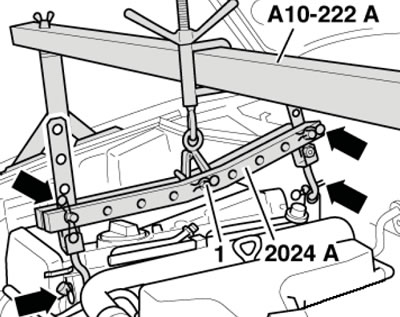
36.7. Hanging the engine
8. On models with independent/additional heating, unscrew the bolts (arrows in illustration 5.4) its exhaust pipe from the soundproofing screen.
9. Unscrew the fasteners (1 and 2 in Illustration 5.5) and remove the front sound insulation screen. Where available, loosen the quick-release couplings (3) and remove the rear sound insulation screen.
10. Unscrew the fastener of the soundproofing screen holder (see illustration 5.6).
11. Place a container underneath to collect the oil and unscrew the bolts (see illustration) and disconnect the return pipe from the oil pan.
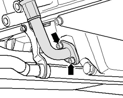
36.11. Fastening of the return oil pipe
12. Disconnect the engine oil level and temperature sensor connector (see illustration 36.1c), installed on the oil pan.
13. Remove the bolt securing the refrigerant line bracket to the oil pan (see illustration 5.48).
14. Disconnect the connector (1 in illustration 5.49) the wiring of the electromagnetic clutch of the air conditioning system compressor, unscrew the bolts (arrows) securing the compressor to the bracket and hang the compressor on the body without disconnecting the refrigerant lines from it.
15. Remove the bolt securing the refrigerant line bracket to the oil pan (see illustration 5.48).
16. Disconnect the connector (1 in illustration 5.49) the wiring of the electromagnetic clutch of the air conditioning system compressor, unscrew the bolts (arrows) securing the compressor to the bracket and hang the compressor on the body without disconnecting the refrigerant lines from it.
17. Remove the bolts (see illustration 16.14) and remove the engine jet support.
18. If equipped, separate the front left suspension height sensor link from the lower control arm (see illustration).
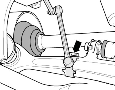
36.18. Suspension height sensor rod on the lower arm
36.18. Suspension height sensor rod on the lower arm
19. Remove the bolts (1 and 2 in illustration 16.15) and remove the stabilizer bar supports.
20. Cut the starter wiring clamps (see illustration 16.16) and remove the wiring. Support the front subframe from below with a transmission jack.
21. Give the nut (3 in illustration 16.17) at the bottom of the engine mount, remove the bolts (4 and 5) of the engine mount console and the front bolt (1) of the subframe. Remove the engine mount console (2) and repeat this procedure on the other side of the engine.
22. Slowly lower the subframe on the transmission jack and pull the engine up a little on the crossmember No.10-222A/11 (see illustration 36.7).
23. Remove the transmission mounting bolts to the oil pan (see illustration 5.52).
24. Unscrew the M10 bolts (arrows in illustration 16.21) and loosen the bolts (1-18) crosswise.
25. Using an extension, remove the two rear oil pan mounting bolts (1 and 2 in the illustration). To do this, on models with a manual transmission, turn the dual mass flywheel until the notch (arrow) is opposite the bolt.
26. Remove all bolts and remove the oil pan, tapping it lightly with a rubber-faced hammer if necessary.
27. Installation is performed in the reverse order of dismantling the components. Please note the following features.
28. Prepare the following new parts: oil pan gasket, lip seals, sealing rings and bolts/screws tightened to a certain angle. Remove any remaining sealant from the mating surfaces of the oil pan and cylinder block, clean all seating surfaces from oil and grease.
29. Apply a 2-3 mm diameter bead of sealant to the clean surface of the oil pan as shown in the illustration 27.39.
Note: In the area of the threaded holes, the sealant bead must run on the inside: in the area of the rear sealing flange (arrows), the sealant must be applied especially carefully. The balance shaft module must be installed within 5 minutes of applying the sealant.
30. Immediately after applying the sealant, install the oil pan and tighten its mounting bolts as shown in the illustration 16.21 sequence in several stages: first bolts 1-18 - crosswise with a force of 5 Nm, then - bolts fastening the pan to the transmission with a force of 45 Nm, then - bolts M10 (arrows) with a force of 40 Nm, and finally - bolts 1-18 crosswise with a force of 15 Nm.
31. When installing the oil pan (3 in illustration 16.36) on the removed engine, pay attention to the fact that the pallet should be flush with the intermediate shield (1), i.e. the pallet should protrude beyond the cylinder block (2) by the size (a) = 0.8 mm. After installation, the sealant should dry for about 30 minutes. Only then can you fill in the engine oil.
32. Install the subframe (see Chapter 10) and jet thrust.
Removal and installation the oil pump
33. Remove the oil pan (see subsection above) and oil soother.
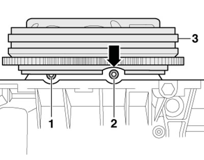
34. Unscrew the bolt (1 in the illustration), remove the sprocket from the pump shaft, unscrew the bolts (1 and 3) and remove the oil pump.
36.34. Fastening the oil pump
35. Installation is performed in the reverse order of component dismantling. The sprocket can only be installed on the pump shaft in one position. Tighten the oil pump mounting bolts to 10 Nm.
Removal and installation the oil cooler and oil filter bracket
a36. Drain the coolant and remove the upper coolant pipe (see Chapter 3).
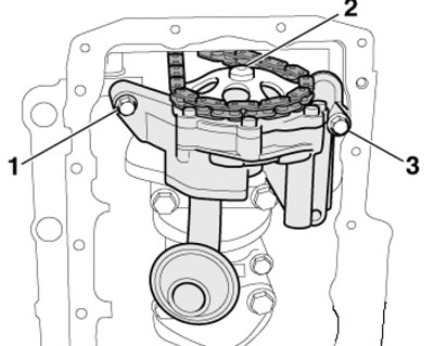
37. Place a container underneath to collect the oil and unscrew the oil filter (1 illustration). Note the position of the oil cooler (2) and remove it.
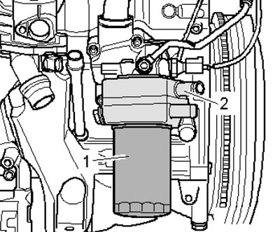
36.37. Fastening the oil filter and oil cooler
38. Disconnect the electrical wiring connector (3 in the illustration), unscrew the bolt (1) securing the feed tube to the filter bracket, remove the retainer (2) and remove the PCV tube. Unscrew the bolts (arrows) and remove the oil filter bracket.
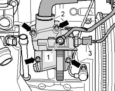
36.38. Fastening the oil filter bracket
39. Installation is carried out in the reverse order of dismantling the components. Use new gaskets and sealing rings.
(This article was previously published on the resource: AUDIMANUAL.RU)