
Table of contents: Lower section of the oil pan of the… ↓ Upper section of the oil pan of the… ↓ Oil pump for 2.8L petrol engine ↓
Lower section of the oil pan of the 2.8L petrol engine
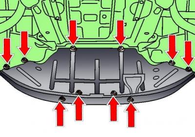
Fig. 3.1–1. Location of the engine compartment lower mudguard mounting fasteners
Release the fasteners and remove the soundproofing panel (see Fig. 3.1–1)
Place a container under the engine to collect the engine oil and drain it motor oil.
Cars with automatic transmission
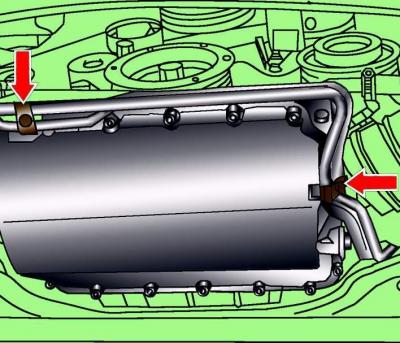
Fig. 3.1–26. Location of bolts for fastening the brackets supporting the pipes to the automatic transmission
Unscrew the two bolts (see Fig. 3.1–26) securing the pipe brackets to the automatic transmission.
All models
Unscrew the bolts securing the lower section of the oil pan and remove it.
Installation is carried out in the reverse order of removal, taking into account the following.
Use a plastic or wooden scraper to clean the old gasket from the mating surfaces of the upper and lower sections of the oil pan
Tighten the oil pan mounting bolts evenly diagonally, first to 5 Nm, then finally to 10 Nm.
Pour into the engine motor oil.
Upper section of the oil pan of the 2.8L petrol engine
Before disconnecting the battery, find out if you have a radio activation code.
Turn off the ignition and disconnect the ground wire from the battery.
Remove the engine oil level indicator (dipstick).
Remove the lower section of the oil pan.
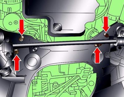
Fig. 3.1–31. Location of engine mounting bolts to the lower frame
Unscrew the lower bolts (see Fig. 3.1–31) securing the engine to the lower frame.
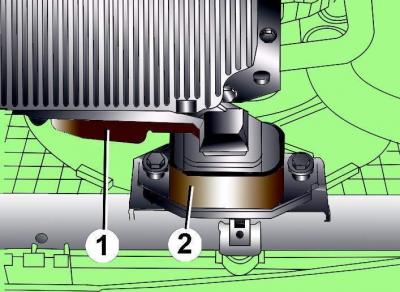
Fig. 3.1–30. Location of the engine torque compensator support: 1 – support; 2 – limiter
Unscrew the mounting bolts of support 1 (see Fig. 3.1–30) of the engine torque compensator and, moving the support, remove it.
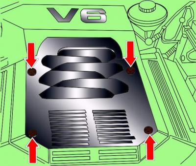
Fig. 3.1–41. Location of engine casing mounting screws
Remove the four screws and remove the engine cover (see Fig. 3.1–41).
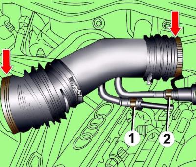
Fig. 3.1–42. Location of the clamps for fastening the air flow meter air pipe and the intake pipe: 1 – fuel supply pipe; 2 – fuel supply hose
Loosen the clamps and remove the air pipe connecting the air flow meter and the suction pipe (see Fig. 3.1–42).
Disconnect the electrical connectors from the Hall sensor and the spark plug of the fifth cylinder.
Cars with cruise control
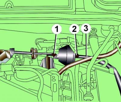
Fig. 3.1–14. Location of control rod (1), vacuum block mounting nut (2) and vacuum hose (3)
Disconnect control rod 1 (see Fig. 3.1–14) from the vacuum block.
Remove vacuum hose 3 from the vacuum block.
Unscrew nut 2 and remove the vacuum block.
All models
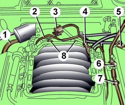
Fig. 3.1–6. Hoses location on top of engine: 1 – crankcase ventilation hose; 2, 4, 6, 7 – vacuum hoses; 3 – valve for switching the suction pipeline; 5 – connection of the vacuum hose to the brake booster; 8 – screws for fastening the air pipe of the throttle assembly
Disconnect the crankcase ventilation hoses from the right and left cylinder head covers (see Fig. 3.1–6).
Unscrew the valve (see Fig. 3.1–6) to switch the suction pipe and move it together with the pipe to the side.
Carefully remove the vacuum hoses (see Fig. 3.1–6).
Loosen the screws (see Fig. 3.1–6) and remove the air pipe from the throttle body.
Disconnect the electrical connector from the coolant temperature sensor G2.
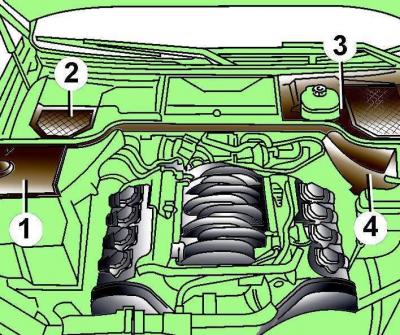
Fig. 3.1–7. Location of protective covers (1–4) in the rear of the engine compartment
Remove the protective covers at the rear of the engine compartment (see Fig. 3.1–7).
Prepare a 10-222A/4 adapter and a 10-222A lifting device with clamps to support the engine.
Install the 10–222A/4 adapter and 10–222A lifting device onto the front suspension strut supports.
Secure the lifting device clamp to the engine.
By turning the screws of the lifting device, tighten the clamp so that the weight of the engine is supported by the lifting device.
Clamp the cooling system hoses near the oil cooler.
Place a container under the engine to collect the fluid.
Disconnect the hoses from the oil heat exchanger.
Place a container under the oil filter to collect the engine oil.
Remove the oil filter.
Remove the oil heat exchanger.
Remove the transmission-to-engine mounting bolts near the top section of the oil pan.
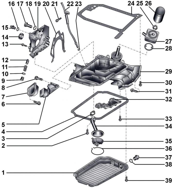
Fig. 6–17. Elements of the lubrication system of a 2.8 L gasoline engine: 1 – lower section of the oil pan; 2 – bolt, 10 Nm; 3 – gasket; 4 – gasket; 5 – torque compensator; 6 – bolt, 40 Nm; 7 – Torque compensator support; 8 – bolt, 42 Nm; 9 – threaded plug, 45 Nm; 10 – sealing ring; 11 – pressure relief valve spring; 12 – pressure relief valve piston; 13 – bolt, 10 Nm; 14 – crankshaft oil seal; 15 – oil temperature sensor G8, 10 Nm; 16 – sealing ring; 17 – threaded plug, 30 Nm; 18 – sealing ring; 19 – oil pump; 20 – gasket; 21 – bolt, 10 Nm; 22 – guide tube for engine oil level indicator (dipstick); 23 – sealing ring; 24 – gasket; 25 – bolt, 30 Nm; 26 – oil filter, 20 Nm; 27 – oil heat exchanger; 28 – gasket; 29 – Upper section of the oil pan; 30 – bolt, 10 Nm; 31 – bolt, M8 – 25 Nm, M10 – 45 Nm; 32 – cover; 33 – bolt, 10 Nm; 34 – oil receiver pipe; 35 – oil receiver housing; 36 – retaining ring; 37 – oil drain plug, 40 Nm; 38 – gasket; 39 – bolt, 10 Nm
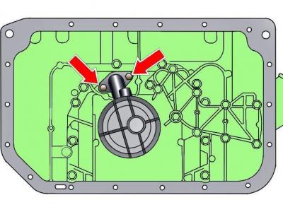
Fig. 6–18. Location of bolts securing the oil pickup pipe to the oil pump
If present, unscrew the bolts securing the oil pickup pipe to the oil pump (Fig. 6–18).
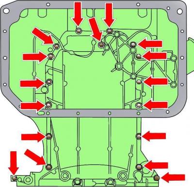
Fig. 6–19. Location of oil pan upper section mounting bolts
Unscrew the bolts securing the upper section of the oil pan (Fig. 6–19).
Remove the upper section of the oil pan from the cylinder block centering bushings.
Disconnect the electrical connectors from the oil pressure sensors.
Move the top section of the oil pan down and remove it from underneath the vehicle.
Installation is carried out in the reverse order of removal, taking into account the following.
Use a plastic or wooden scraper to remove the old gasket from the mating surfaces of the upper and lower sections of the oil pan.
New gaskets and sealing rings must be used during installation.
Before screwing in the bolt threads (see Fig. 6–19), apply the locking compound D 000 600 A2 to prevent them from loosening.
Tighten the upper oil pan section mounting bolts evenly diagonally, first to 5 Nm, then finally to 10 Nm.
Screw in and tighten the bolts securing the upper section of the oil pan to the gearbox to the torque: M8 – 25 Nm, M10 – 45 Nm.
Install the lower section of the oil pan.
Pour into the engine motor oil.
Fill the cooling system with coolant.
Connect the ground wire to the battery.
Turn on radio and enter the code into it.
Raise the power windows all the way up. Then press all power window switches again for at least 1 second to the closed position to activate the power window control unit.
Set the time on the clock.
Oil pump for 2.8L petrol engine
Remove the timing belt.
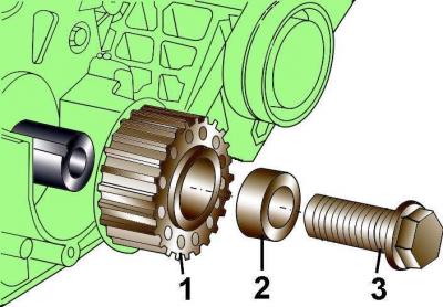
Fig. 3.1–63. Crankshaft pulley fastening elements: 1 – crankshaft toothed belt pulley; 2 – spacer sleeve; 3 – bolt
Unscrew bolt 3 (see Fig. 3.1–63) securing the crankshaft pulley.
Remove the upper section of the oil pan.
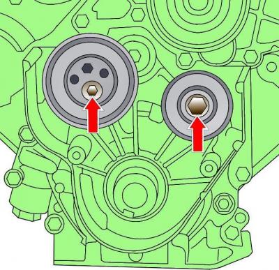
Fig. 6–20. Location of idler and tension roller mounting bolts
Unscrew the bolts securing the idler and tension rollers (Fig. 6–20).
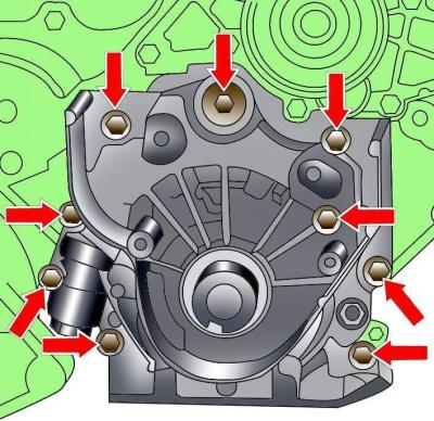
Fig. 6–21. Location of oil pump mounting bolts
Unscrew the bolts and remove the oil pump (Fig. 6–21).
Installation is carried out in the reverse order of removal, taking into account the following.
Clean the mating surfaces of the oil pump and the engine cylinder block, install the oil pump and secure it with bolts.
Install a new front crankshaft oil seal, lubricating its working edge and outer surface with engine oil.
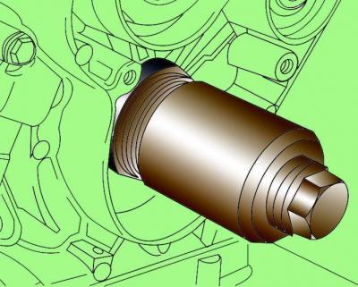
Fig. 3.1–65. Using the 3265 drift to install the front crankshaft oil seal ring
Using drift 3265 (see Fig. 3.1–65), install the oil seal onto the crankshaft and, using the pulley mounting bolt, press it into the socket.
Install pulley 1 (see Fig. 3.1–63) of the crankshaft toothed belt, spacer sleeve and screw in the fastening bolt. There should be no grease on the bearing surface between the pulley and the crankshaft. Do not lubricate the crankshaft pulley fastening bolt.
When installing, it is necessary to use a new crankshaft pulley mounting bolt.
Install the timing belt.
Install the upper section of the oil pan.
Install the lower section of the oil pan.