
Table of contents: Lower section of the oil pan of the… ↓ Diesel Engine Oil Pump 2.5L ↓
Lower section of the oil pan of the 2.5L diesel engine
Remove the cap from the expansion tank.
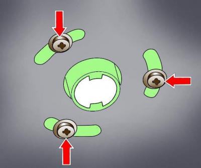
Fig. 3.3–34. Location of the exhaust pipe heater mounting screws and additional heater sound insulation
Unscrew the screws securing the exhaust pipe heater and the additional heater sound insulation (see Fig. 3.3–34).
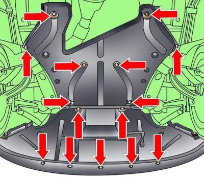
Fig. 3.3–35. Location of engine compartment lower mudguard mounting fasteners
Release the fasteners and remove the front section of the lower engine compartment mudguard (see Fig. 3.3–35).
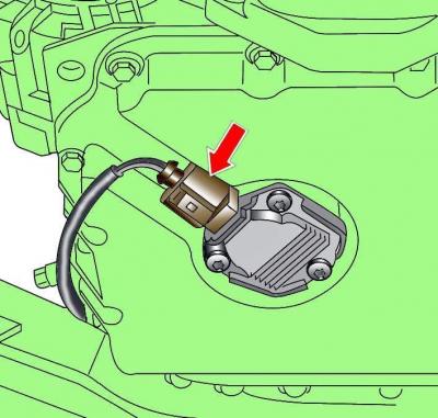
Fig. 6–3. Location of the electrical connector for the engine oil level sensor
Disconnect the electrical connector from the oil level sensor (Fig. 6-3).
Place a container under the engine to collect the coolant.
Unscrew the plug and drain the coolant.
Unscrew the bolt securing the coolant drain pipe holder to the cylinder block.
Place a container under the engine to collect the engine oil.
Drain motor oil, to do this, loosen the oil drain plug by about half a turn. Place a container to collect the oil under the drain plug and unscrew the plug completely. If necessary, press on the plug when unscrewing it so that the oil does not flow out prematurely.
When the oil has completely drained, screw the plug back in.
Remove the bolts and remove the lower section of the oil pan.
Installation is carried out in the reverse order of removal.
Note: New O-rings must be used during installation.
On engines with a gasket on the lower section of the oil pan, check the condition and location of the gasket.
Use a plastic or wooden scraper to remove the old gasket from the mating surfaces of the upper and lower sections of the oil pan.
Using a rotating wire brush attached to a power drill, clean the sealant from the oil pan.
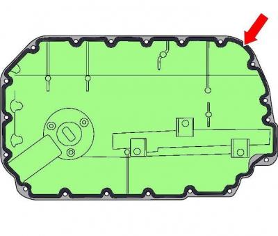
Fig. 6–4. Place where a 3 mm diameter layer of sealant is applied to the mating surface of the oil pan
Apply a 3 mm bead of D176 404 A2 sealant to the oil pan mating surface (Fig. 6–4).
After applying a layer of sealant, the oil pan must be installed within 5 minutes, the sealant must be allowed to dry for 30 minutes, and only then poured into the engine motor oil.
The sealant layer should be no more than 3 mm in diameter, as excess sealant may get into the oil and block the mesh filter.
Tighten the oil pan mounting bolts evenly and diagonally.
On engines with a gasket on the lower section of the oil pan, do not overtighten the bolts as this will distort the oil pan gasket.
On engines where the lower section of the oil pan is installed with sealant, tighten the mounting bolts first to 5 N·m, then finally to 10 N·m.
Fill with coolant.
Pour into the engine motor oil.
Diesel Engine Oil Pump 2.5L
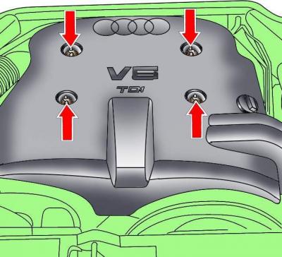
Fig. 3.3–24. Location of engine casing mounting screws
Loosen the screws and remove the engine casing (see Fig. 3.3–24).
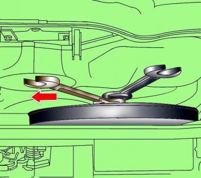
Fig. 3.3–26. Unscrewing the mounting bolt of the radiator fan with a viscous coupling
Loosen the viscous coupling radiator fan mounting bolt, holding the fan shaft from turning with an additional wrench (see Fig. 3.3–26).
Remove the bolts located at the top in front of the radiator and remove the radiator fan shroud.
Remove the viscous coupling fan together with the casing.
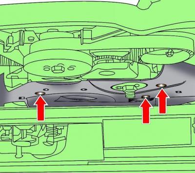
Fig. 3.3–27. Location of the poly V-belt cover mounting screws
Loosen the screws and remove the poly V-belt cover (see Fig. 3.3–27).
Remove the cap from the expansion tank.
Remove the oil filler cap.
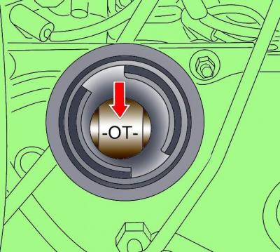
Fig. 3.3–33. Mark on the camshaft when setting the piston of the first cylinder to TDC of the compression stroke
Using the pulley mounting bolt, turn the crankshaft in the direction of working rotation until the "OT" (TDC) mark appears on the camshaft in the oil filler neck hole (see Fig. 3.3–33).
Loosen the screws securing the exhaust pipe heater and the additional heater sound insulation (see Fig. 3.3–34).
Release the fasteners and remove the front section of the lower engine compartment mudguard (see Fig. 3.3–35).
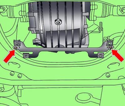
Fig. 3.3–36. Location of engine compartment lower mudguard bracket mounting bolts
Unscrew the two bolts and remove the soundproofing panel bracket (see Fig. 3.3–36)
Remove the lower section of the oil pan.
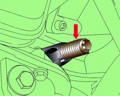
Fig. 3.3–37. Location of the 3242 set screw for fixing the crankshaft
Lock the crankshaft in this position by unscrewing the plug from the cylinder block and screwing in the set screw 3242 instead (see Fig. 3.3–37).
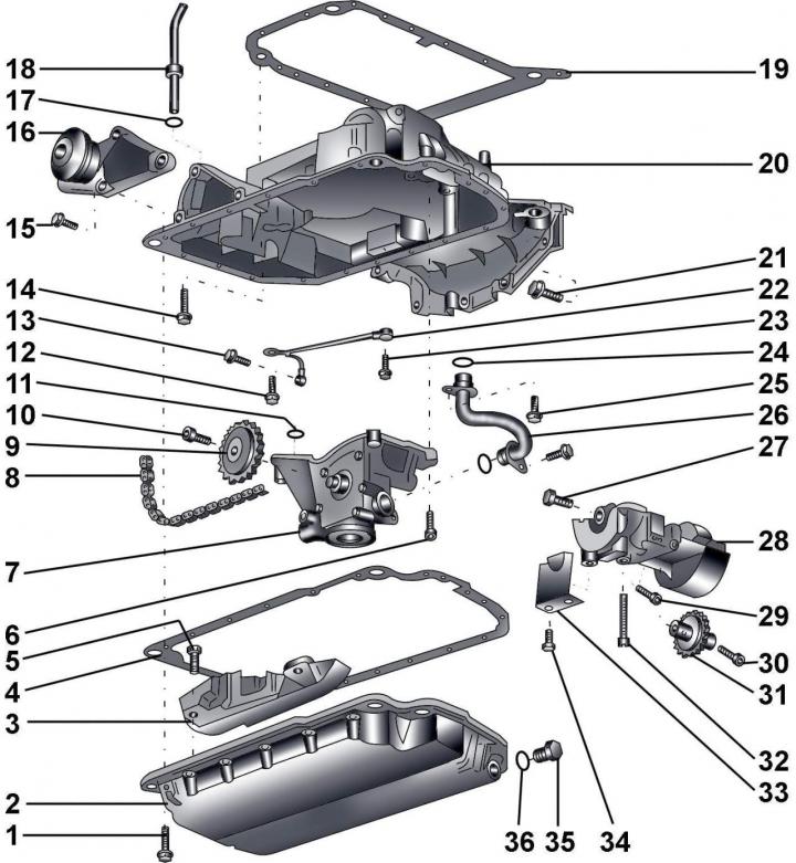
Fig. 6–2. Elements of the lubrication system of a 2.5 L diesel engine: 1 – bolt, 10 Nm; 2 – lower section of the oil pan; 3 – chain cover; 4 – gasket; 5 – bolt, 10 Nm; 6 – bolt, 22 Nm; 7 – oil pump with pressure regulating valve (3.8 bar), with safety valve (11 bar); 8 – chain; 9 – oil pump sprocket; 10 – bolt, 22 Nm; 11 – sealing ring; 12 – bolt, 10 Nm; 13 – hollow bolt, 10 Nm; 14 – bolt; 15 – bolt, 45 Nm; 16 – torque compensator; 17 – sealing ring; 18 – guide tube for engine oil level indicator (dipstick); 19 – gasket; 20 – Upper section of the oil pan; 21 – bolt, 45 Nm; 22 – oil line from the oil pump to the balance shaft; 23 – hollow bolt, 10 Nm; 24 – sealing ring; 25 – bolt, 10 Nm; 26 – pressure oil line; 27 – bolt, 45 Nm; 28 – casing with balance shaft; 29 – bolt, 10 Nm; 30 – bolt, 10 Nm; 31 – asterisk; 32 – bolt, 22 Nm; 33 – partition; 34 – bolt, 10 Nm; 35 – oil drain plug, 25 Nm; 36 – sealing ring
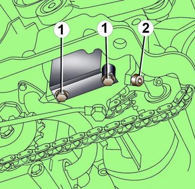
Fig. 6–5. Location of bulkhead mounting bolts (1) and plug bolt (2)
Unscrew the two bolts and remove the partition (Fig. 6–5).
Unscrew the plug bolt 2 and replace it with the set screw 3204, which secures the balancing shaft.
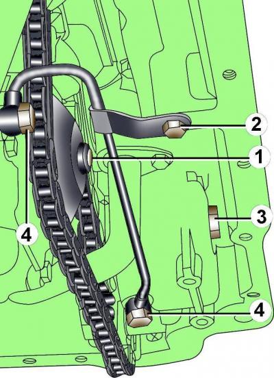
Fig. 6–6. Location of bolts for fastening oil lines and sprockets of the oil pump and balance shaft on a 2.5 L diesel engine: 1 – oil pump sprocket mounting bolt; 2 – oil line bracket mounting bolt; 3 – balance shaft sprocket mounting bolt; 4 – hollow bolts for fastening the oil line
Loosen, but do not remove, bolt 1 of the oil pump sprocket (see Fig. 6–6).
Loosen, but do not remove, the balance shaft sprocket mounting bolt (see Fig. 6–6).
Unscrew the hollow bolts 4 securing the oil pump oil line and the balance shaft, as well as the bolt 2 securing the oil line bracket and remove the oil line.
Unscrew the two bolts and remove the oil pressure line.
Unscrew the bolts securing the intermediate chain sprocket and remove it.
Remove the bolts and remove the sprocket from the oil pump shaft.
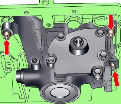
Fig. 6–7. Location of oil pump mounting bolts on a 2.5L diesel engine
Unscrew the bolts and remove the oil pump (Fig. 6–7).
Install the oil pump in the reverse order of removal, taking into account the following.
Check that set screws 3242 and 3204 are in place.
Tighten the oil pump sprocket mounting bolt.
Install the lower section of the oil pan.
Install the radiator fan with viscous coupling.