
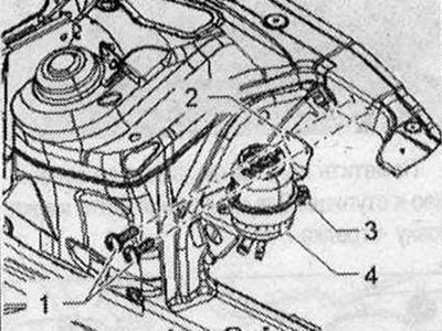
Vehicles with 4-cyl. diesel engine, vehicles with dynamic steering system installation
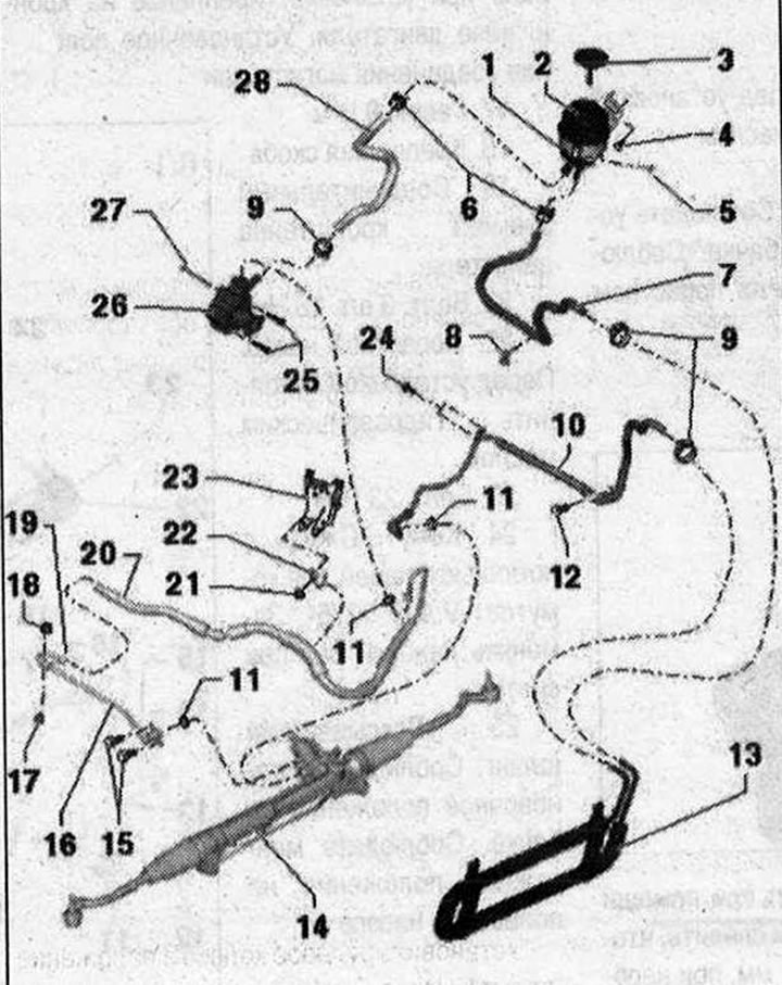
I 1. Bandage. Mounting on the body; 2. Expansion tank. Pay attention to the installation position. Installation position of hose lines on the tank; 3. Locking cap with measuring probe; 4/5/12/24. Bolt. 9 Nm; 6. Spring clamp. Remove and install using hose clamp pliers -VAG 1921-; 7. Return hose from the hydraulic oil cooler to the expansion tank. tank. Mounting on the spar. Observe the installation position on the tank. Observe the installation position on the hydraulic oil cooler; 8. Clamp; 9. Clamp. Press together using clamp pliers -VAG 1275-. After installation, ensure correct fixation. Replace each time when removed; 10. Return line from the power steering mechanism to the hydraulic oil cooler. Insert the return line all the way during installation. Mounting on a subframe. Observe the installation position on the hydraulic oil cooler. Mounting position on line connection; 11. Seal ring. Replace each time when removed; 13. Hydraulic oil cooler. Fixed on the capacitor using a clip; 14. Power steering; 15. Bolt. 20 Nm; 16. Pressure line from the vane pump to the power steering gear. Insert the pressure line all the way during installation.; 17. Rubber cushion. 6 Nm; 18. Nut..6 Nm; 19. Union nut. 40 Nm; 20. Pressure line from the vane pump to the power steering gear. Insert the pressure line all the way during installation. Observe the installation position: the angle between the line connection and the axis of the vane pump is approx. 90°. Union nut tightening torque: 38 Nm. Mounting on engine bracket; 21. Nut. 9 Nm; 22. Mounting bracket; 23. Engine bracket connecting element; 25. Bolt. 3 pcs. 23 Nm; 26. Vane pump. Before installation, fill with hydraulic oil; 27. Bolt. 23 Nm; 28. Suction hose. Observe the installation position on the tank. Observe the installation position on the vane pump
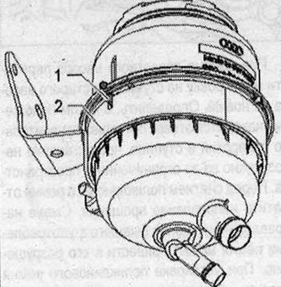
Clamp installation location
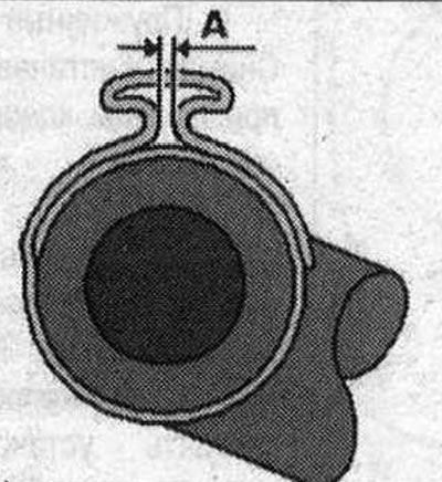
Tighten the clamp completely using pliers -VAG 1275-. Make sure that dimension -A- does not exceed 1 mm; if necessary, tighten the clamp using pliers -VAG 1275-.
Vehicles with 4-cyl. diesel engine, vehicles without dynamic steering system installation
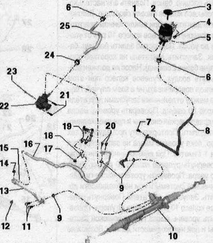
I 1. Bandage; 2. Expansion tank. Pay attention to the installation position. Installation position of hose lines on the tank; 3. Locking cap with measuring probe; 4/5/7/20. Bolt. 9 Nm; 6. Spring clamp. Remove and install using hose clamp pliers -VAG 1921-; 8. Return line from the power steering gearbox to the reservoir. Insert the return line all the way during installation. Mounting on a subframe. Observe the installation position on the tank; 9. Seal ring. Replace each time when removed; 10. Power steering; 11. Bolt. 20 Nm; 12. Rubber cushion. 6 Nm; 13. Pressure line from the vane pump to the power steering gear. Insert the pressure line all the way during installation. Attachment of guy wires to the crosspiece. Installation position of the trunk connection; 14. Nut. 6 Nm; 15. Union nut. 40 Nm; 16. Pressure line from the vane pump to the power steering gear. Insert the pressure line all the way during installation. Mounting on engine bracket. Installation position of the trunk connection; 17. Nut. 9 Nm; 18. Mounting bracket; 19. Engine bracket connecting element; 21. Bolt. 3 pcs. 23 Nm; 22. Vane pump. Before installation, fill with hydraulic oil; 23. Bolt. 23 Nm; 24. Clamp. Press together using clamp pliers -VAG 1275-. Replace each time when removed; 25. Suction hose. Observe the installation position on the tank. Observe the installation position on the vane pump
Vehicles with 4-cyl. diesel engine, vehicles with and without dynamic steering system, pipes and hoses
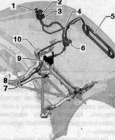
Parts and assemblies, fasteners for pipelines and hoses 1. Tank bracket on the body; 2. Tank in bracket; 3. Bracket bolt; 4. The return hose clamp is on the side member and the suction hose clamp is on the pressure tube; 5. Hydraulic fluid radiator to condenser; 6. Vane pump in bracket; 7. Pressure line on the cross brace; 8. Installation position of the pressure line connection; 9. Pressure line on the engine bracket; 10. Return line on the subframe, return line bracket on the side member
Bracket for tank on body
The bracket -1 is attached with bolts -2- to the body. Secure the tank -4- with a bolt -3- in the bracket -2-.
Tank in bracket
Place the reservoir with the protrusion -1 - into the recess on the bracket -2-.
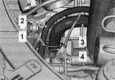
Return hose clamp on side member
Secure return hose -1- using clamp -2- to left side member.
Suction hose in pressure tube clamp
Insert suction hose -1- into clamp -2- of pressure pipe -3-.
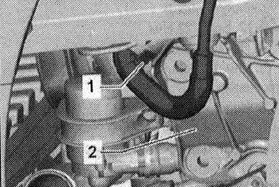
Hydraulic fluid radiator to condenser
Install the hydraulic fluid cooler -1- onto the brackets -2-, then secure it into the brackets -3-. Lines to the hydraulic fluid radiator.
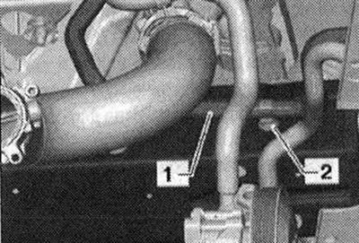
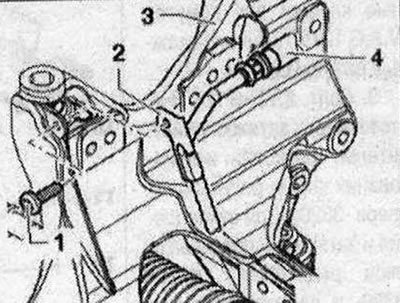
Pressure line on the cross brace
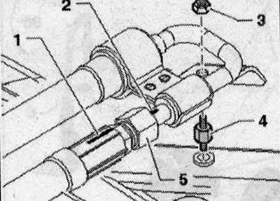
Screw the pressure line using a nut -3- and a rubber support -4- onto the cross connection of the braces. When screwing in the line connection, take into account the installation position of the line. Marks -1- and -2- must be located opposite each other.
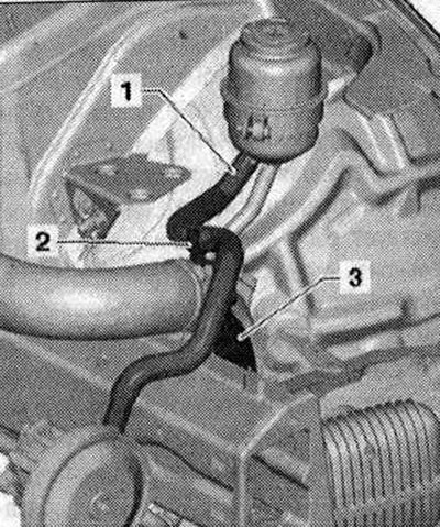
Pressure line on engine bracket
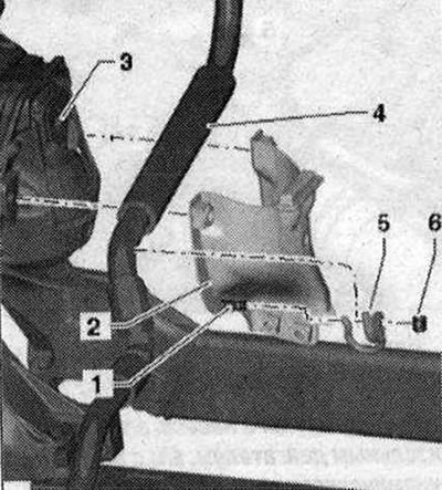
Route pressure line -4- between connecting piece -2- and engine bracket -3-. Screw the mounting bracket -5- with a nut -6- onto the threaded pin-1-.
Return line holder on subframe
Secure the return line with holder -1- at the front left to the subframe -2-.
Return line on subframe
Secure the return line -4- with holder -2- and bolt -1 - to the subframe -3-.
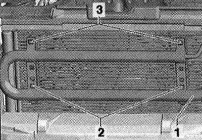
Radiator hydraulic lines to radiator frame
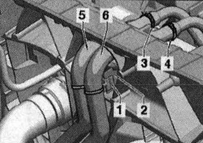
Place lines -5- and -6- with clips -1 - (2 pcs.) on the ledges -2- (2 pcs.).
Removing the vane pump, vehicles with 4-cyl. diesel engine, vehicles with dynamic steering system
Replace seal. rings. Do not reuse drained hydraulic oil. Use only hydraulic oil.
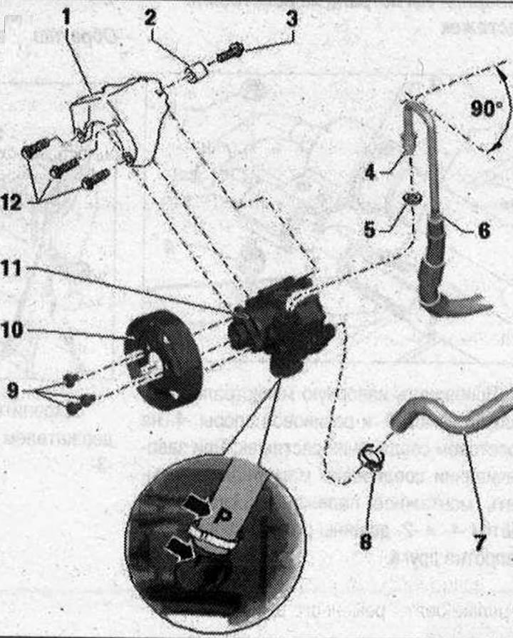
I 1. Holder; 2. Bushing. To install the vane pump, the sleeve must be moved back slightly; 3/12. Bolt. 23 Nm; 4. Union nut. 38 Nm; 5. Seal ring. Replace each time when removed; 6. Pressure line. Insert the pressure line all the way during installation. Observe the installation position: the angle between the line connection and the axis of the vane pump is approx. 90°; 7. Suction hose. Marking "R" -arrow- on the suction hose must be aligned with the profiled seam -arrow- on the vane pump; 8. Clamp. Press together using clamp pliers -VAG 1275-. Replace each time when removed; 9. Bolt. 23 Nm. 20 Nm, this tightening torque only applies when using the door adjustment key -3320-. To unfasten and tighten, use the door adjustment key -3320- and the corresponding bit -3320/2-; 10. Pulley; 11. Vane pump. Fill with hydraulic oil before installation
Bleed the air from the steering. Check the level of working fluid in the hydraulic system.
Check steering tightness
Removal
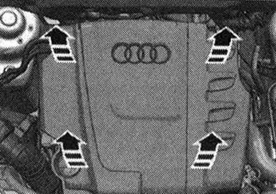
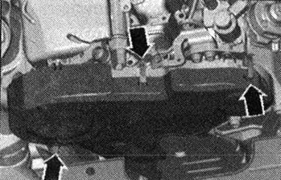
Repair work for the vane pump is not provided. In the event of complaints, the cause must be determined by means of a pressure test and a leak test. If there is a malfunction, the vane pump should be replaced. If there is no working fluid in the reservoir, it is necessary to check the tightness of the steering. If there is no seal near the line connections, first check the lines/line connections for leaks, tighten if necessary and wipe dry. The vane pump is supplied unprimed. Therefore, before installation, be sure to fill the pump with hydraulic fluid and turn it by hand. Otherwise, operating noise or damage to the vane pump may occur. Place the vehicle on a lift. Remove engine cover upwards -arrows-.
Release clamps -arrows- and remove toothed belt cover.
Mark the position of the pulley in relation to the hub. To do this, mark -arrow-.
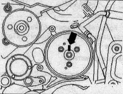
When replacing a vane pump, transfer the markings on the hub from the old pump to the new one. It is impossible to determine in what position the pulley holes are located relative to the holes in the hub during installation due to limited space. Before removing the poly V-belt, note the direction of rotation. Changing the direction of rotation of a used belt can lead to its destruction. When installing the poly V-belt, ensure that it is positioned correctly on the pulleys. Remove the poly V-belt from the vane pump pulley only. First, simply loosen the pulley bolts -arrow- using the door adjustment key -3320- and the corresponding bit -3320/2-. If necessary, use counter support -T10172- with adapter -T10172/5- -1- for this purpose.
Unscrew the loosened bolts and remove the pulley. Pump out hydraulic fluid from the reservoir using a waste oil collection and pumping device.
Clamp suction hose -1- and return hose -2- using hose clamps up to 025 mm -3094-.
Do not attach hose clamps up to 025 mm -3094- to the return hose -2- near the check valve. Otherwise, the check valve may be damaged.
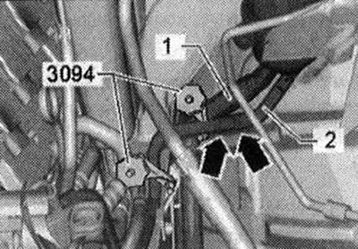
The non-return valve is located in the return hose -2- between the clamps -arrows-.
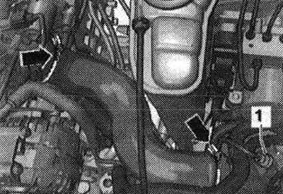
Loosen the hose clamps -arrows- and disconnect the air inlet hose. Remove sound insulation. Place a tray under the vane pump.
Cut carefully (in the presence of) cable ties -1- wiring harness -2-. Remove the clamp -4- from the suction hose -3-. Remove suction hose -3-. Place a rag under the vane pump and pressure line.
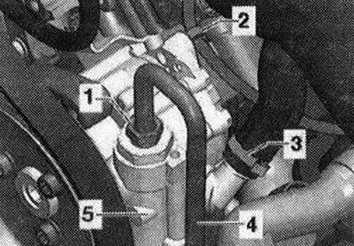
Unscrew the union nut -1 - and remove the pressure line -4- from the vane pump. Close the connections of the vane pump and the line with clean plugs.
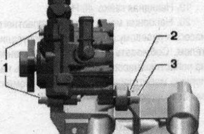
If present, unclip wiring harness -2- at vane pump. Remove bolts -1 - (3 pcs.) and bolt -3-. To install the vane pump, it is necessary to slightly move back the bushing -2- of the bolt -3- in the bracket. Remove the vane pump.
Installation
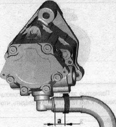
Install in reverse order. In this case, tightening torques must be taken into account. Replace seals and seals. rings. Before installing a new vane pump, fill the suction side with hydraulic oil and turn it by hand until the oil comes out on the pressure side. Secure all hose connections with new clamps. Observe the installation position of the suction hose on the vane pump. Pay attention to the installation size of the clamp. Dimension -a- should be 4 mm.
Turn the hub by hand until oil comes out from the pressure side. Insert the vane pump into the bracket. The bushing -2- is slightly pushed back. Do not fully tighten the front bolts -1- first (3 pcs.). Then tighten the rear bolt -3-. First tighten bolts -1- and then bolt -3-. Press the pressure line -4- into the vane pump -5- as far as it will go. Finally, tighten the union nut -1-. When installing the pressure line -4-, make sure that the angle between the line connection and the axis of the vane pump is approx. 90°. Place the suction hose onto the connection and install a new clamp -3-. Clean oily areas in the motor. compartment Align the marking -arrow- on the belt pulley with the marking on the hub. Tighten -arrows- belt pulley bolts. Install the vane pump serpentine belt. Check the level of working fluid in the hydraulic system. Bleed the air from the steering. Check the steering for leaks. Install sound insulation. Install the poly V-belt and check the alignment of the poly V-belt. When installing the poly V-belt, ensure that it is seated correctly in the pulleys.
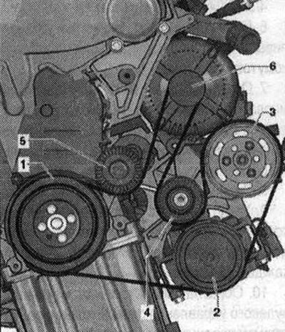
- 1. Vibration damper
- 2. Air conditioning compressor 3. Vane pump pulley
- 4. Guide roller
- 5. Poly V-belt tensioner
- 6. Generator
Turn on the engine and check the running of the V-ribbed belt.
Visitor comments