
Table of contents: Vehicles with 6-cyl. FSI engine,… ↓ Removal the vane pump, vehicles with… ↓ Removal ↓ Installation ↓ Removal the vane pump, vehicles with… ↓ Mounting position of hose lines on… ↓
Note. Repair work for the vane pump is not provided. In case of complaints, the cause must be determined by pressure testing and leak testing. If a fault is found, the vane pump must be replaced. If there is no working fluid in the reservoir, the steering must be checked for leaks. If there is no leakage near the line connections, first check the lines/line connections for leaks, tighten them if necessary and wipe dry. The vane pump is supplied unfilled. Therefore, before installation, it is imperative to fill the pump with hydraulic fluid and turn it by hand. Otherwise, noise may occur during operation or the vane pump may be damaged.
Vehicles with 6-cyl. FSI engine, vehicles without dynamic steering system
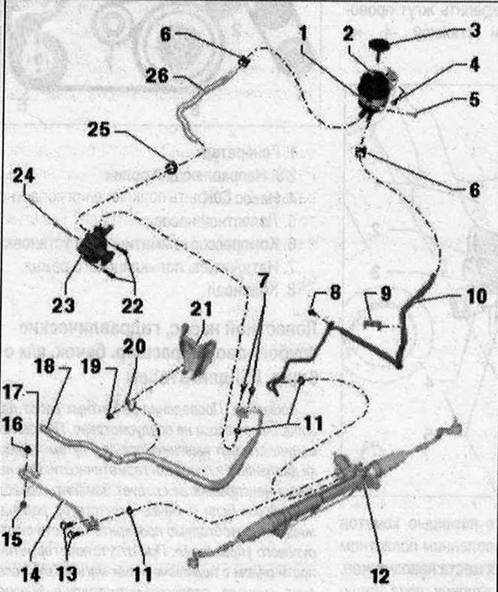
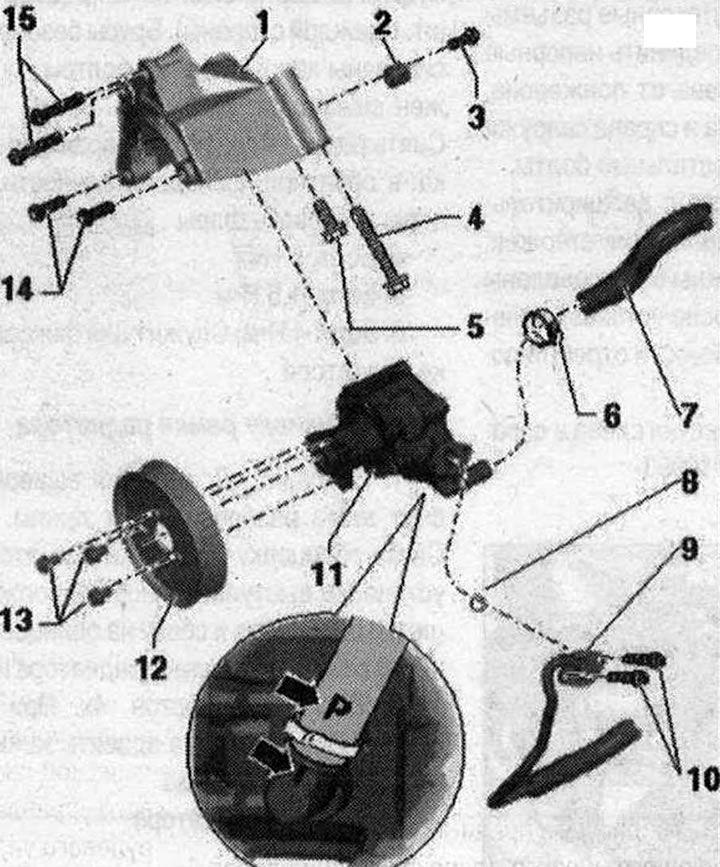
I 1. Bandage; 2. Expansion tank. Consider the installation position. Installation position of the hose lines on the tank; 3. Locking cap with measuring probe; 4/577/8. Bolt. 9 Nm; 6. Spring clamp. Remove and install with hose clamp pliers "V.A.G 1921"; 9. Line holder. For fastening the suction hose to the side member; 10. Return line from the power steering gear to the reservoir. Insert the return line all the way during installation; 11. Subframe mounting. Observe installation position on reservoir. Sealing ring. Replace each time when removing; 12. Power steering 13/22/24. Bolt. 20 Nm; 14. Pressure line from vane pump to power steering gear. Insert pressure line fully during installation; 15. Rubber cushion. 6 Nm; 16. Nut. 6 Nm; 17. Union nut. 40 Nm; 18. Pressure line from vane pump to power steering gear. Insert pressure line fully during installation; 19. Nut. 9 Nm; 20. Mounting bracket; 21. Engine bracket connecting element; 23. Vane pump. Fill with hydraulic oil before installation; 25. Clamp. Tighten with clamp pliers "V.A.G 1275". Replace each time when removed; 26. Suction hose. Observe installation position on tank. Observe installation position on vane pump
Removal the vane pump, vehicles with 6-cyl. FSI engine, vehicles with dynamic steering system
Replace the sealing rings. Do not reuse drained hydraulic oil. Use only hydraulic oil.
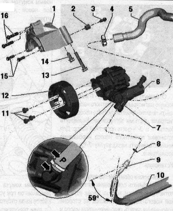
II 1. Holder; 2. Bushing. To install the vane pump, the bushing needs to be moved back a little; 3/13/14/16. Bolt. 20 Nm; 4. Clamp. Press with clamp pliers "V.A.G 1275". Replace each time when removed; 5. Suction hose. The "P" "arrow" marking on the suction hose must be aligned with the profiled seam "arrow" on the vane pump; 6. Vane pump regulating valve (V119). The vane pump and regulating valve are a single unit and are replaced only as a set; 7. Hydraulic steering pump "V119" with vane pump regulating valve (V119). The vane pump and regulating valve are a single unit and are replaced only as an assembly. Fill with hydraulic oil before installation. Bleed the steering. Check the working fluid level in the hydraulic system; 8. Sealing ring. Replace each time when removed; 9. Union nut. 38 Nm. 36 Nm, this tightening torque is only valid in combination with a 17 mm open-end ring spanner "V.A.G 1331/10"; 10. Pressure line. Insert the pressure line completely during installation. Observe the installation position: the angle between the line connection and the axis of the vane pump is approx. 59°. Depending on the version, additionally fastened to the compressor; 11. Bolt. 22 Nm; 12. Pulley; 15. Bolt. 20 Nm. For fastening the vane pump to the bracket.
Removal
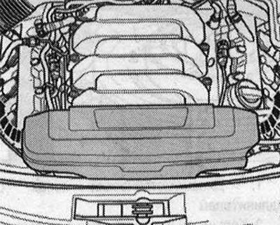
Repair work for the vane pump is not provided. In case of complaints, the cause should be determined by pressure testing and leak testing. If a fault is found, the vane pump should be replaced. If there is no working fluid in the reservoir, the steering system should be checked for leaks. If there is no leakage near the line connections, first check the lines/line connections for leaks, tighten them if necessary and wipe dry. The vane pump is supplied unfilled. Therefore, before installation, it is necessary to fill the pump with hydraulic fluid and turn it by hand. Otherwise, noise may occur during operation or the vane pump may be damaged. Place the car on a lift. Remove the engine casing in the upward direction of the "arrows".
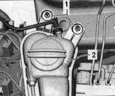
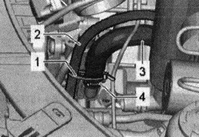
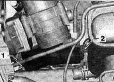
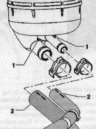
Pump out the hydraulic fluid from the reservoir using a device for collecting and pumping out waste oil. Clamp the suction hose "1" and the return hose "2" with hose clamps up to 025 mm "3094".
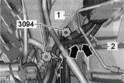
It is prohibited to fix clamps for hoses up to 025 mm "3094" on the return hose "2" near the check valve. Otherwise, the check valve may be damaged. The check valve is located in the return hose "2" between the clamps, "arrows". Remove the sound insulation. Unscrew the nuts "1" and remove the expansion tank of coolant "2" with the connected lines. Unlock the plug connector on the expansion tank of coolant "2" and disconnect.
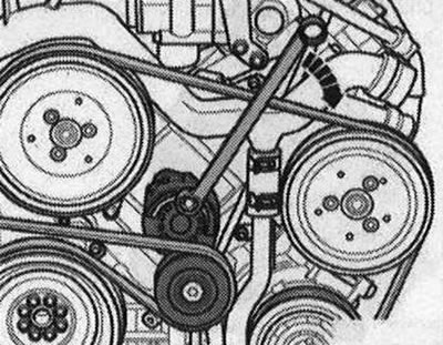
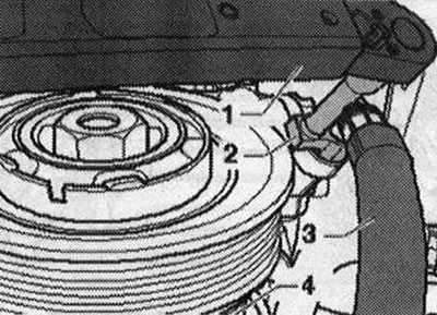
Before removing the poly V-belt, mark the direction of rotation. Changing the direction of rotation of a used belt can lead to its destruction. When installing the poly V-belt, ensure that it is correctly positioned on the pulleys. Turn the tensioner to loosen the poly V-belt in the direction of the "arrow". Remove the poly V-belt only from the vane pump pulley. Loosen the clamp and remove the tool.
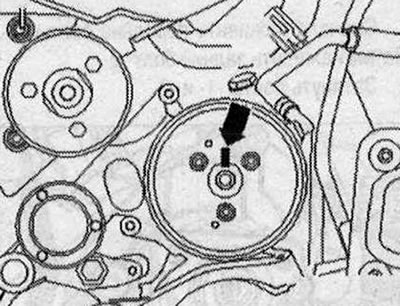
Mark the position of the pulley in relation to the hub. To do this, make a marking "arrow".
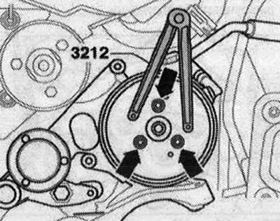
When replacing a vane pump, transfer the marking on the hub from the old pump to the new one. It is impossible to determine the position of the pulley holes relative to the holes in the hub during installation due to limited space. Unscrew the bolts "arrows". Use a 2-hole wrench "3212" to hold them. Remove the vane pump belt pulley. Install a tray under the vane pump.
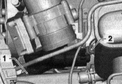
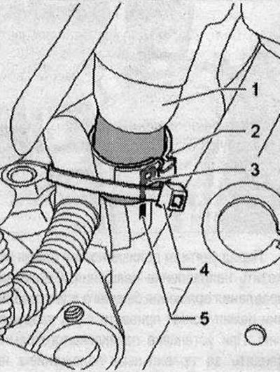
If present, carefully cut the cable clamp "1" of the wiring harness "2". Remove the clamp "4" from the suction hose "3". Remove the suction hose "3".
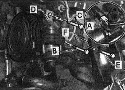
If the pressure line is additionally secured to the air conditioning compressor, unscrew bolt "C" of bracket "D" of the air conditioning compressor.
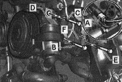
Unscrew the union nut "1" and remove the pressure line from the vane pump. Unlock and disconnect the plug connector "2". Close the connections of the vane pump and the line with clean plugs.
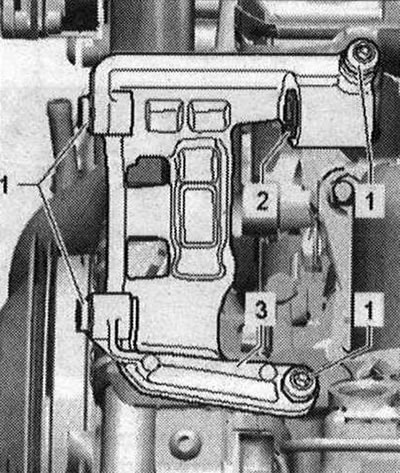
Unscrew the vane pump fasteners from the bracket. To do this, unscrew bolts "1" in the front and bolts "2" in the back. Bolt "2" is not visible in the bracket; it is shown in the unscrewed position in the figure.
Remove the vane pump.
Installation
Installation in reverse order. The following must be taken into account: to install the vane pump, it is necessary to slightly move the sleeve "2" in the bracket back. Do not take into account positions "1 and 3".
Replace seals and O-rings. Before installing a new vane pump, fill the suction side with hydraulic oil and turn it by hand so that the oil comes out on the discharge side. Secure all hose connections with new clamps. It is impossible to tighten clamp "2" with hose clamp pliers when the vane pump is installed due to limited space. Before installing the vane pump, put on suction hose "1" and align the "P" mark "3" with the "-5" mark on the vane pump. Secure suction hose "1" with a new clamp "2". If installed, secure the wire harness with a new cable binder "4" to the nipple.
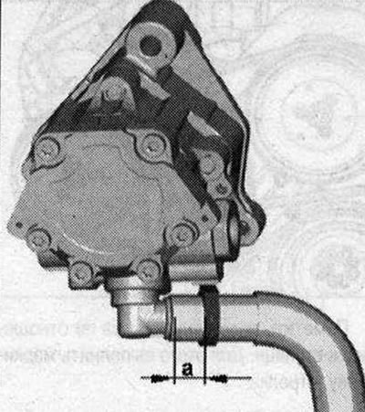
Pay attention to the installation size of the clamp. The size "a" should be 4 mm. Insert the vane pump into the bracket.
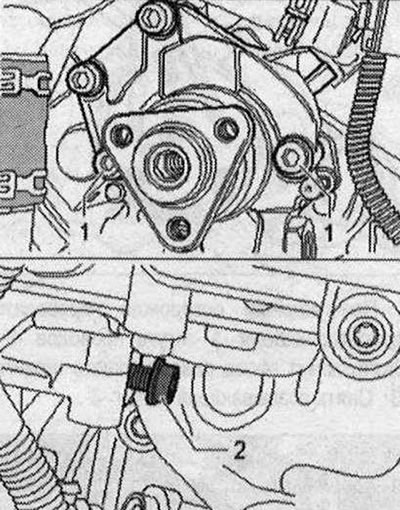
First, tighten the front bolts "1".
Then tighten the rear bolt "2".
Tighten bolts "1" and "2".
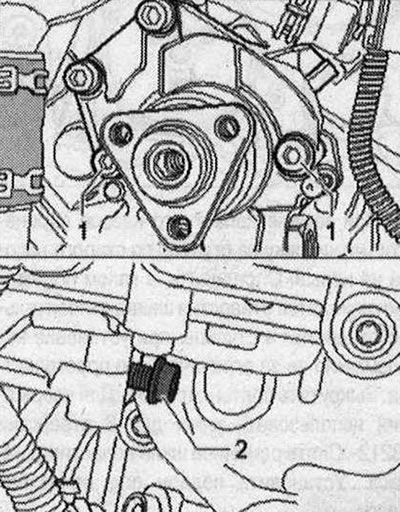
Make sure the suction hose is properly secured (twisting/bending). Turn the hub by hand until oil comes out from the discharge side. Press the discharge line into the vane pump until it stops. Then screw on the union nut "1". Install the plug connection "2".
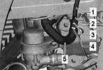
Tighten the union nut with an open-end union nut size SW 17 "V.A.G 1331/10", as shown in the figure.
- 1. Torque wrench with extension
- 2. Ring spanner with open end for 17 "V.A.G 1331/10"
- 3. Pressure line with union nut
- 4. Air conditioning compressor If the pressure line is additionally secured to the air conditioning compressor, tighten bolt "C" of bracket "D" of the air conditioning compressor. Clean oily areas in the engine compartment.
Align the applied "arrow" marking on the belt pulley with the marking applied to the hub. Tighten the "arrow" bolts of the belt pulley. Install the poly V-belt of the vane pump. Check the level of the working fluid in the hydraulic system. Bleed air from the steering. Check the tightness of the steering. Install noise insulation. Install the poly V-belt and check the alignment of the poly V-belt. When installing the poly V-belt, ensure that it is correctly seated in the pulleys.
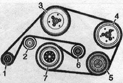
- 1. Generator
- 2. Guide roller
- 3. Coolant pump
- 4. Vane pump
- 5. Air conditioning compressor
- 6. Tension roller
- 7. Crankshaft
Removal the vane pump, vehicles with 6-cyl. FSI engine, vehicles without dynamic steering system
Replace the sealing rings. Do not reuse drained hydraulic oil. Use only hydraulic oil.
I 1. Holder; 2. Bushing. To install the vane pump, the bushing needs to be moved back a little; 3. Bolt 20 Nm; 4/5. Bolt. 20 Nm. For fixing the bracket to the engine. Consider the different lengths of the bolts; 6. Clamp. Tighten with clamp pliers "V.A.G 1275". Replace each time when removed; 7. Suction hose. The "P" "arrow" marking on the suction hose must be aligned with the profiled "arrow" seam on the vane pump; 8. Sealing ring. Replace each time when removed; 9. Depending on the variant, the pressure line is additionally attached to the compressor. Insert the pressure line completely during installation; 10. Bolt. 9 Nm; 11. Vane pump. Fill with hydraulic oil before installation. Bleed air from the steering. Check the level of working fluid in the hydraulic system; 12. Pulley; 13. Bolt. 22 Nm; 14. Bolt. 20 Nm. For fastening the vane pump to the bracket; 15. Bolt. 20 Nm. For fastening the bracket to the engine.
Mounting position of hose lines on reservoir, hydraulic fluid radiator and return line
The installation position of the hose lines on the power steering oil reservoir is valid for all engine types. There should be no traces of oil or grease at the connection points; clean if necessary. The markings "2" on the hose lines should be aligned with the ribs -1 on the reservoir. Position the clamp locks in the direction of travel from the front.
Mounting position of hose lines on the hydraulic fluid radiator: The connection points must be free of oil and grease, clean if necessary. The "2" markings on the hose lines must be facing upwards towards the "12 o'clock" point.
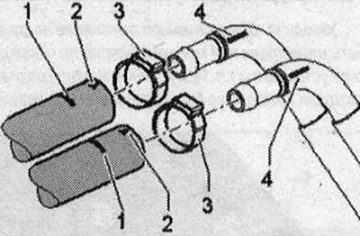
When installing hose lines "1", hold tubes "4" from turning. Fasten clamps "3" to markings 1.
Mounting position on the return line connection: The connection points must be free of oil and grease, clean if necessary. Marking "3" of the hose line "5" must be opposite marking "2" of the pipe line. Fasten the clamp (not shown in the picture) on the marking "4".
Clamp installation location: Tighten the clamp completely using pliers "V.A.G 1275". In this case, make sure that the size of the clamp does not exceed 1 mm; if necessary, tighten the clamp with pliers "V.A.G 1275".