
Table of contents: Vehicles with 6-cyl. diesel engine,… ↓ Mounting position of the clamping… ↓ Vehicles with 6-cyl. diesel engine,… ↓ Removal the vane pump, vehicles with… ↓ Removal ↓ Installation ↓
Note. Repair work for the vane pump is not provided. In case of complaints, the cause must be determined by pressure testing and leak testing. If a fault is found, the vane pump must be replaced. If there is no working fluid in the reservoir, the steering must be checked for leaks. If there is no leakage near the line connections, first check the lines/line connections for leaks, tighten them if necessary and wipe dry. The vane pump is supplied unfilled. Therefore, before installation, it is imperative to fill the pump with hydraulic fluid and turn it by hand. Otherwise, noise may occur during operation or the vane pump may be damaged.
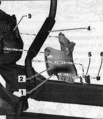
Vehicles with 6-cyl. diesel engine, vehicles with dynamic steering system
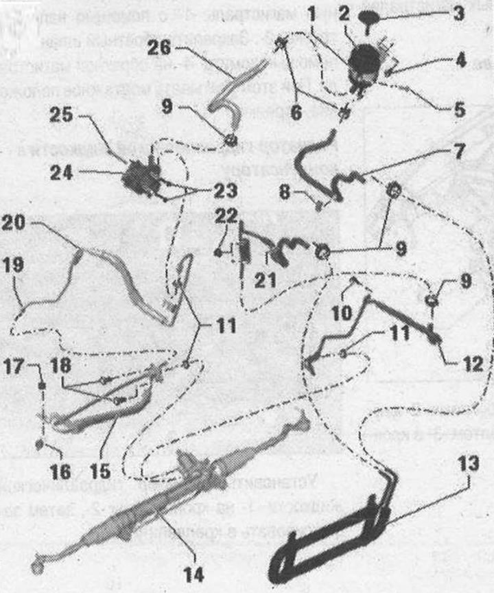
I 1. Bandage; 2. Expansion tank. Consider the installation position; 3. Locking cap with measuring probe; 4/5/10. Bolt. 9 Nm; 6. Spring clamp. Remove and install with hose clamp pliers "V.A.G 1921"; 7. Return hose from the hydraulic fluid radiator to the tank, there should be no traces of oil or grease at the connection points, clean if necessary. Observe the installation position on the tank. Observe the installation position on the hydraulic oil cooler; 8. Clamp; 9. Clamp. Tighten with clamp pliers "V.A.G 1275". After installation, make sure it is properly secured. Replace each time you remove it; 11. Sealing ring. Replace each time when removed; 12. The return line from the power steering to the hydraulic fluid radiator, there should be no traces of oil or grease at the connection points, clean if necessary. Insert the return line all the way when installing; 13. The hydraulic oil cooler should be free of oil and grease at the connection points, clean if necessary. It is fixed to the condenser with a clip; 14. Power steering; 15. Pressure line from vane pump to power steering gear. Insert pressure line fully during installation; 16. Rubber cushion. 6 Nm; 17. Nut. 6 Nm; 18. Bolt. 20 Nm; 19. Union nut. 40 Nm; 20. Pressure line from vane pump to power steering. Insert pressure line fully during installation. Observe installation position: angle between line connection and vane pump axis is approx. 88°; 21. Return line from the power steering to the hydraulic fluid radiator, there should be no traces of oil or grease at the connection points, clean if necessary. Insert the pressure line completely during installation. Observe the installation position on the hydraulic oil cooler; 22. Nut. 9 Nm; 23. Bolt. 23 Nm; 24. Vane pump. Fill with hydraulic oil before installation; 25. Bolt. 23 Nm. 20 Nm, this tightening torque is only valid when using the door adjustment key "3320". For loosening and tightening, use the door adjustment key "3320" and the corresponding bit "3320/2"; 26. Suction hose. There should be no traces of oil or grease at the connection points, clean if necessary. Observe the installation position on the tank. Observe the installation position on the vane pump
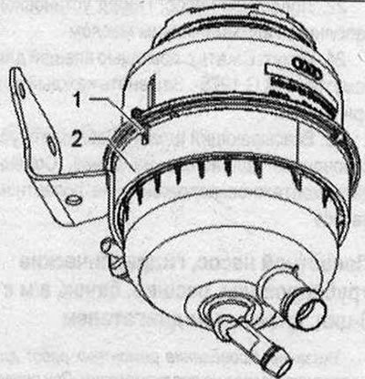
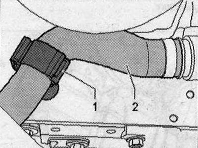
Mounting position of the clamping clamp
Tighten the clamp completely using pliers "V.A.G 1275". In this case, make sure that the size "A" does not exceed 1 mm; if necessary, tighten the clamp with pliers "V.A.G 1275".
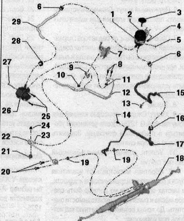
Vehicles with 6-cyl. diesel engine, vehicles without dynamic steering system 1. Bandage; 2. Expansion tank. Consider the installation position; 3. Locking cap with measuring probe; 4/5/8/14. Bolt. 9 Nm; 6. Spring clamp. Remove and install with hose clamp pliers "V.A.G 1921"; 7. Engine bracket connecting element; 9. Mounting bracket; 10. Nut. 9 Nm; 11. Sealing ring. Replace each time when removed; 12. Pressure line from vane pump to power steering gear. Insert pressure line fully during installation; 13. Clamp; 15. Return hose from the hydraulic fluid radiator to the tank, there should be no traces of oil or grease at the connection points, clean if necessary. Observe the installation position on the tank. Observe the installation position on the hydraulic oil cooler; 16. Clamp. Tighten with clamp pliers "V.A.G 1275". After installation, make sure it is properly secured. Replace each time you remove it; 17. Return line from the power steering to the reservoir, there should be no traces of oil or grease at the connection points, clean if necessary. Insert the return line all the way during installation; 18. Power steering; 19. Sealing ring. Replace each time when removed; 20. Bolt. 20 Nm; 21. Rubber cushion. 9 Nm; 22. Pressure line from vane pump to power steering gear. Insert pressure line fully during installation; 23. Union nut. 40 Nm. Installation position of the line connection; 24. Nut. 6 Nm; 25. Bolt. 23 Nm; 26. Vane pump. Fill with hydraulic oil before installation; 27. Bolt. 23 Nm. 20 Nm, this tightening torque is only valid when using the door adjustment key "3320". For loosening and tightening, use the door adjustment key "3320" and the corresponding bit "3320/2"; 28. Clamp. Tighten with clamp pliers "V.A.G 1275". After installation, make sure it is properly secured. Replace each time you remove it; 29. Suction hose. There should be no traces of oil or grease at the connection points; clean if necessary. Observe the installation position on the tank. Observe the installation position on the vane pump
Vehicles with 6-cyl. diesel engine, vehicles with and without dynamic steering system, pipes and hoses
Parts and assemblies, fasteners for pipelines and hoses
- 1. Tank bracket on the body
- 2. Tank in bracket
- 3. Bracket bolt
- 4. Hydraulic fluid radiator to condenser
- 5. Vane pump in bracket
- 6. Pressure main on the crosspiece of the stretchers
- 7. Installation position of the pressure line connection
- 8. Pressure line on the engine bracket
- 9. Return line on the subframe
- 10. Brackets of return lines on the subframe and side member
Tank bracket on the body
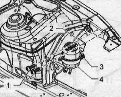
Bracket "1" is fastened to the body with bolts "2". Fasten tank "4" with bolt "3" in bracket "2".
Tank in bracket
Install the tank with the protrusion "1" into the recess on the bracket "2".
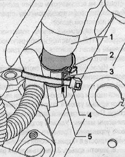
Bracket of highways on the side member
On the left side member, secure the return line "1" using the pressure pipe "2". Secure the return hose "5" using the clamp "4" on the return line. In doing so, take into account the installation position of the "arrow".
Hydraulic fluid radiator to condenser
Install the hydraulic fluid radiator "1" on the brackets "2", then secure it in the fasteners "3".
Pressure main on the crosspiece of the stretchers
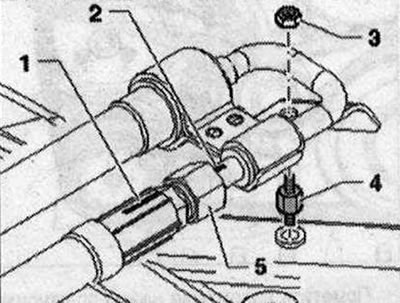
Screw the pressure main line using nut "3" and rubber support "4" on the cross connection of the braces. When screwing the main line connection, take into account the installation position of the main line. Marks "1" and "2" must be located opposite each other.
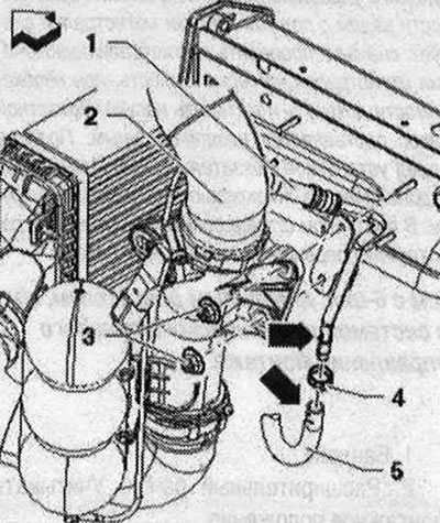
Pressure line on the engine bracket
Lay the pressure line "4" between the connecting element "2" and the engine bracket "3". Screw the fastening bracket "5" with the nut "6" onto the threaded pin "1".
Return line holder on subframe
Secure the return line with the holder "1" at the front left on the subframe "2".
Pressure and return lines to the subframe
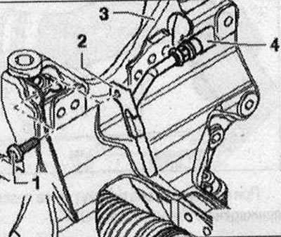
Secure the return line "4" with the holder "2" and bolt "1" to the subframe "3".
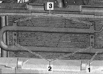
Radiator hydraulic fluid lines to radiator frame
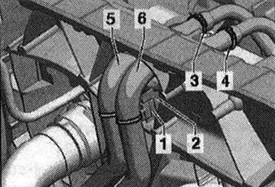
Place the lines "5" and "6" with the clamps "1" (2 pcs.) on the protrusions "2" (2 pcs.)
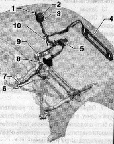
Removal the vane pump, vehicles with a 6-cyl. diesel engine, vehicles with a dynamic steering system
Replace the sealing rings. Do not reuse drained hydraulic oil. Use only hydraulic oil.
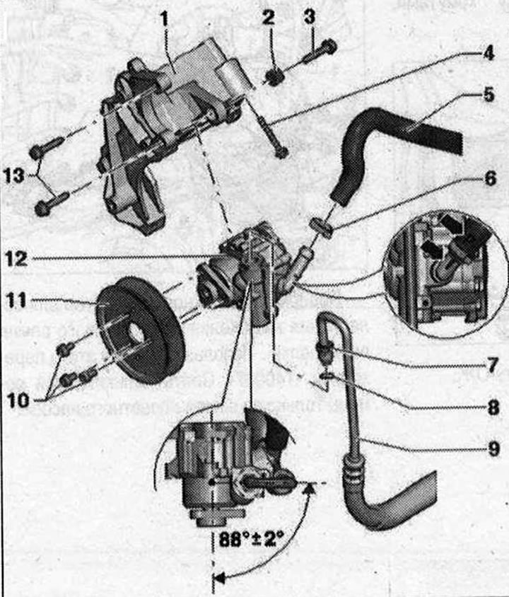
I 1. Holder; 2. Bushing. To install the vane pump, the bushing needs to be moved back a little; 3. Bolt. 23 Nm. 20 Nm, this tightening torque is only valid when using the door adjustment key "3320". For loosening and tightening, use the door adjustment key "3320" and the corresponding bit "3320/2"; 4. Bolt; 5. Suction hose. The "P" "arrow" marking on the suction hose must be aligned with the profiled seam "arrow" on the vane pump; 6. Clamp. Tighten with clamp pliers "V.A.G 1275". Replace each time when removed; 7. Union nut. 38 Nm; 8. Sealing ring. Replace each time when removed; 9. Pressure line. Insert the pressure line completely during installation. Observe the installation position: the angle between the line connection and the axis of the vane pump is approx. 88°. Depending on the version, additionally fastened to the compressor; 10. Bolt. 23 Nm; 11. Pulley; 12. Vane pump. Before installation, fill with hydraulic oil and remove air from the steering. Check the level of working fluid in the hydraulic system. Check the tightness of the steering; 13. Bolt. 23 Nm
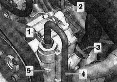
Removal
Repair work for the vane pump is not provided. In case of complaints, the cause must be determined by pressure testing and leak testing. If a fault is found, the vane pump must be replaced. If there is no working fluid in the reservoir, the steering must be checked for leaks. If there is no leakage near the line connections, first check the lines/line connections for leaks, tighten them if necessary and wipe dry. The vane pump is supplied empty. Therefore, before installation, it is necessary to fill the pump with hydraulic fluid and turn it by hand. Otherwise, noise may occur during operation or the vane pump may be damaged. Place the car on a lift. Pump out the hydraulic fluid from the reservoir using a device for collecting and pumping out used oil. Carefully remove the engine casing from each of the 4 "arrow" pins in turn.
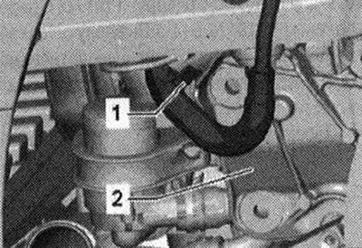
Clamp the suction hose "1" and the return hose "2" with hose clamps up to 25 mm "3094".
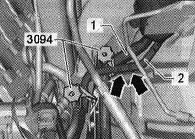
It is prohibited to fix the clamps for hoses up to? 25 mm "3094" on the return hose "2" next to the check valve. Otherwise, the check valve may be damaged. The check valve is located in the return hose "2" between the clamps, "arrows".
Remove sound insulation. Drain coolant.
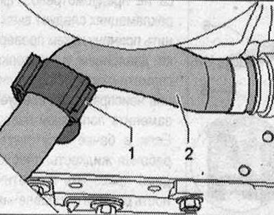
If available, loosen clamp "1" on the left side member and remove coolant hose "2".
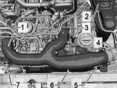
Remove the upper part of the intake manifold "1". To do this, remove the air duct hose "4", eyelet "3", clamp "7" and coolant hose. Remove the coolant expansion tank "2".
Secure the air duct hose "1" with wire "2" to the brake line "3".
Before removing the poly V-belt, mark the direction of rotation. Changing the direction of rotation of a used belt can lead to its destruction. When installing the poly V-belt, ensure that it is correctly positioned on the pulleys.
Turn the tensioner to loosen the poly V-belt in the direction of the "arrow". Use the adapter "T40087" for this. Remove the poly V-belt only from the vane pump pulley.
Mark the position of the pulley in relation to the hub. To do this, make a marking "arrow".
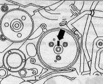
When replacing a vane pump, transfer the markings on the hub from the old pump to the new one. It is impossible to determine the position of the pulley holes relative to the holes in the hub during installation due to limited space.
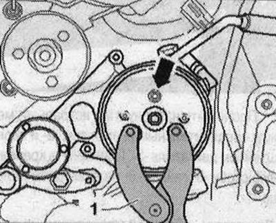
First, simply loosen the pulley "arrow" bolts. If necessary, use the "T10172" counter support with the "T10172/5-1" adapter for this. Unscrew the loosened bolts and remove the pulley from the vane pump. Install a tray under the vane pump.
Cut the binder "4".
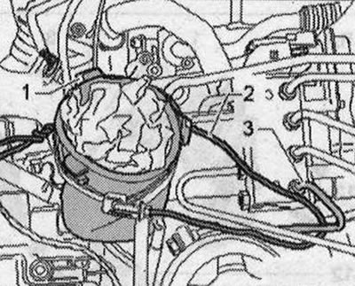
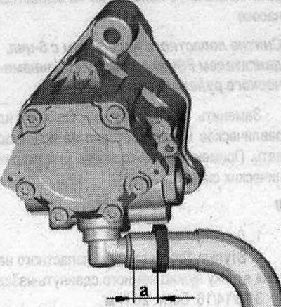
The picture shows the vane pump removed. Place a rag under the vane pump and the pressure line.
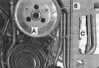
If the pressure line "C" is additionally secured with a bracket on the air conditioner compressor, unscrew the compressor mounting bolt from the front, from above.
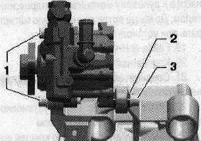
Unscrew the union nut "1" and remove the pressure line from the vane pump. Close the connections of the vane pump and the line with clean plugs. Unscrew the bolts "1" and "3" and remove the vane pump. To install the vane pump, it is necessary to slightly move back the bushing "2" of the bolt 3- in the bracket.
Installation
Installation is in reverse order. The following must be taken into account: replace seals and O-rings. Before installing the new vane pump, fill the suction side with hydraulic oil and turn it by hand so that the oil comes out on the discharge side. Secure all hose connections with new clamps.
Pay attention to the installation size of the clamp. The size "a" should be 4 mm.
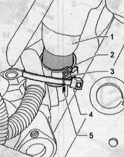
Before installing the vane pump, put on the suction hose "1" and align the "P" mark "3" with the "5" mark on the vane pump. Secure the suction hose "1" with a new clamp "2". Secure the wire harness with a new cable tie "4" on the nipple.
Due to lack of space, it is not possible to secure clamp "2" with hose clamps when the vane pump is installed. Turn the hub by hand until oil emerges from the discharge side. Insert the vane pump into the bracket. Sleeve "2" is pushed back slightly. First, tighten the front bolts "1". Then tighten the rear bolt "3". Tighten bolts "1" and "3". Press the pressure line into the vane pump until it stops. Finally, tighten union nut "1". When installing pressure line "4", ensure that the angle between the line connection and the axis of the vane pump is approximately 88°. (©Picture =
If the pressure line "C" is additionally secured with a bracket on the air conditioning compressor, tighten the compressor mounting bolt at the front, from above. Clean the oily areas in the engine compartment. Align the "arrow" marking on the belt pulley with the marking on the hub. Tighten the "arrow" bolts of the pulley. "1" counter-support "T10172/5". Install the poly V-belt of the vane pump. Fill with coolant and bleed air. Install the upper part of the intake manifold. Check the level of the working fluid in the hydraulic system. Bleed air from the steering. Check the tightness of the steering. Install sound insulation. Install the poly V-belt and check the alignment of the poly V-belt. When installing the poly V-belt, ensure that it is correctly seated in the pulleys.
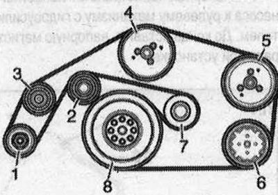
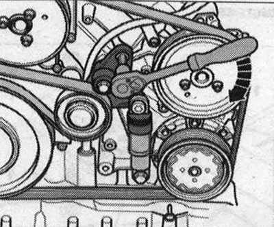
- 1.Generator
- 2/3. Guide roller
- 4. Coolant pump
- 5. Vane pump
- 6. Air conditioning compressor
- 7. Poly V-belt tensioner
- 8. Crankshaft