Repair Chevrolet Repair Toyota Repair Honda Repair AvtoVAZ Repair Mercedes-Benz Repair BMW Repair Opel
Home  |  Contacts  |  Sitemap  |    
English Русский
Български
Беларускі
Український
Српски
Hrvatski
Română
Polski
Slovenský
Magyar
AudiManual.ru


  • AUDI 80
  • AUDI 100
  • AUDI A3
  • AUDI A4
  • AUDI A6
  • AUDI A8
  • AUDI Q
  • OTHER
  • ARTICLES
Q7 Typ 4L (2005-2015, diesel) Q5 Type 8R (2008-2017)

Vane pump, hydraulic lines, expansion tank, vehicle with 4-cylinder TFSI engine (Audi Q5-8R)

  • Home
  • Audi Q
  • Q5 Type 8R (2008-2017)
  • Chassis
  • Steering
  • Vane pump, hydraulic lines, expansion tank, vehicle with 4-cylinder TFSI engine
            0
Note: Repair work on the vane pump is not provided. In case of complaints, the cause must be determined by pressure testing and leak testing. If a fault is found, the vane pump must be replaced. If there is no working fluid in the reservoir, the steering must be checked for leaks. If there is no leakage near the line connections, first check the lines/line connections for leaks, tighten them if necessary and wipe dry. The vane pump is supplied unfilled. Therefore, before installation, it is imperative to fill the pump with hydraulic fluid and turn it by hand. Otherwise, noise may occur during operation or the vane pump may be damaged.


Vehicles with 4-cyl. TFSI engine, vehicles with dynamic steering system
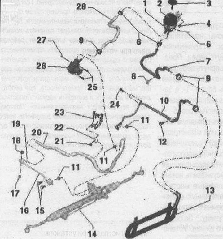


Vane pump, hydraulic lines, expansion tank, vehicle with 4-cylinder TFSI engine

I

1. Bandage. Fastening on the body; 2. Expansion tank. Consider the installation position. Installation position of the hose lines on the tank; 3. Locking cap with measuring probe; 4/5/12/24. Bolt. 9 Nm; 6. Spring clamp. Remove and install with hose clamp pliers "V.A.G 1921"; 7. Return hose from hydraulic oil cooler to expansion tank. Observe installation position on tank. Observe installation position on hydraulic oil cooler; 8. Clamp; 9. Clamp. Tighten with clamp pliers "V.A.G 1275". After installation, make sure it is properly secured. Replace each time you remove it; 10. Return line from the power steering mechanism to the hydraulic oil cooler. Insert the return line fully when installing. Observe the installation position on the hydraulic oil cooler. Installation position on the line connection; 11. Sealing ring. Replace each time when removed; 13. Hydraulic oil cooler. Fixed to the condenser with a clip; 14. Power steering; 15. Bolt. 20 Nm; 16. Pressure line from vane pump to power steering gear. Insert pressure line fully during installation; 17. Rubber cushion. 6 Nm; 18. Nut. 6 Nm; 19. Union nut. 40 Nm; 20. Pressure line from vane pump to power steering. Observe installation position on vane pump. Insert pressure line fully during installation. Tightening torque of union nut: 38 Nm; 21. Nut. 9 Nm; 22. Mounting bracket; 23. Engine bracket connecting element; 25/27. Bolt. 20 Nm; 26. Hydraulic steering pump "V119" with vane pump regulating valve -(V119)-. Pump and regulating valve are one unit and are replaced together. Fill with hydraulic oil before installation; 28. Suction hose. Observe installation position on tank. Observe installation position on vane pump


Clamp installation location


Clamp installation location


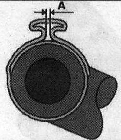
Tighten the clamp completely using pliers "V.A.G 1275". In this case, make sure that the size "A" does not exceed 1 mm; if necessary, tighten the clamp with pliers "V.A.G 1275".

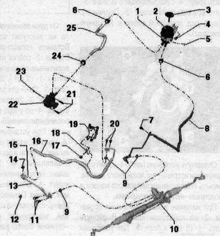
Vehicles with 4-cyl. TFSI engine, vehicles without dynamic steering system


Vane pump, hydraulic lines, expansion tank, vehicle with 4-cylinder TFSI engine

II

1. Bandage; 2. Expansion tank. Consider the installation position. Installation position of the hose lines on the tank; 3. Locking cap with measuring probe; 4/5/7/20. Bolt. 9 Nm; 6. Spring clamp. Remove and install with hose clamp pliers "V.A.G 1921"; 8. Return line from the power steering gear to the reservoir. Observe the installation position on the reservoir. Insert the return line all the way when installing; 9. Sealing ring. Replace each time when removed; 10. Power steering; 11/21/23. Bolt. 20 Nm; 12. Rubber cushion. 6 Nm; 13. Pressure line from vane pump to power steering gear. Insert pressure line fully during installation; 14. Nut. 6 Nm; 15. Union nut. 40 Nm; 16. Pressure line from vane pump to power steering gear. Insert pressure line fully during installation; 17. Nut. 9 Nm; 18. Mounting bracket; 19. Engine bracket connecting element; 22. Vane pump. Fill with hydraulic oil before installation; 24. Clamp. Press with clamp pliers "V.A.G 1275". Replace each time when removed; 25. Suction hose. Observe installation position on tank. Observe installation position on vane pump
The article was checked by auto expert Timur Bazhenov
This article is available at russian, bulgarian, belarusian, ukrainian, serbian, croatian, romanian, polish, slovak, hungarian

Share information:
Previous articles
Audi Q Q5 Type 8R: Steering
Next articles

Vane pump, hydraulic lines, expansion tank, 4-cylinder diesel…
Checking the tightness of the steering system
Bleeding the steering after reinstallation
Checking the power steering fluid level
Vane pump, hydraulic lines, expansion tank, 6-cylinder diesel…
Vane pump, hydraulic lines, expansion tank, vehicles with…


Similar articles on other Audi car models:
Expansion tank cap Audi 80 B4 (1991-1996)
Engine compartment and underbody of 5-cylinder diesel model 2.5L… Audi 100 C3 (1982-1990, diesel)
Fuel tank, fuel pump and fuel filter Audi A3 Type 8L (1996-2003)
Vane pump — vehicles with a 4-cylinder TFSI engine, vehicles… Audi A4 B8 (2007-2015)
Cylinder head — 1.8-I engine (125/150 hp) Audi A6 C5 (1997-2004)
Oil pan and oil pump for 2.5L diesel engine Audi A8 D2 (1994-2002)
Master brake cylinder, expansion tank Audi A2 (1999-2005)
Link to this page in different formats


Visitor comments

No comments yet


How much will 24 + 50 =


Q7 4L(2005-2015, diesel) 
  • General information
  • Operating instructions
  • Maintenance
  • Power unit
  • Diesels 3.0 l (BUG, BUN, CAS)
  • Diesels 3.0 l (CATA, CCMA)
  • Diesels 3.0 l (CJGA/CJGC)
  • Diesels 4.2 l (BTR, CCFA/CCFC)
  • Cooling system
  • Fuel and exhaust system
  • Engine management system
  • Starting and charging
  • Transmission
  • Automatic gearbox
  • Drive shafts
  • Chassis
  • Brake system
  • Front suspension
  • Rear suspension
  • Steering system
  • Body
  • Air conditioner
  • Exterior
  • Interior
  • Electrical equipment
  • Equipment and devices
  • Electrical circuits
 
Q5 8R(2008-2017) 
  • General information
  • User manual
  • Power unit
  • Petrol engine 2.0 l
  • Petrol engine 3.2 l
  • Fuel system (petrol)
  • Diesel 2.0 liter (CA)
  • Diesel 2.0 liter (CG/CJ/CM)
  • Diesel engine 3.0 l
  • Fuel system (diesel)
  • Transmission
  • Manual gearbox 0B1
  • Manual gearbox 0B2
  • Automatic gearbox 0B5
  • Automatic gearbox 0B6
  • Chassis
  • Front suspension
  • Rear suspension
  • Brake system
  • Steering
  • Body
  • Exterior
  • Interior
  • Doors, locks and windows
  • Safety system
  • Ventilation and heating
  • Electrical equipment
  • Power devices
  • Equipment and devices
  • Lighting and alarm
  • Audio system
  • Electrical circuits
 
AudiManual.ru © 2017-2026 · Mobile version · Feedback · Sitemap: EN BG BY UA RS HR RO PL SK HU · Site search · News and articles
80 B2 · 80 B3 petrol · 80 B3 · 80 B4 · 100 C3 diesel · 100 C3 petrol · 100 C3 · 100 C4 petrol · 100 C4 · A3 Type 8L · A4 B5 petrol · A4 B5 · A4 B6 petrol · A4 B6 · A4 B7 · A4 B8 · A6 C4 · A6 C5 · A6 C5 Allroad · A8 D2 · Q5 Type 8R · Q7 Typ 4L · Audi A2 ·
This site uses cookies 🍪. Click the button to accept this fact.